40 3 to 1 pulley system diagram
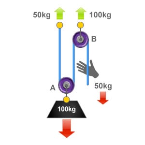
Four-to-one systems are less popular than 3:1 systems, probably because they require an additional pulley and don't offer significantly more mechanical advantage. However once you learn how to stack a 2:1 on a 2:1 to create a compound 4:1, you'll know how to stack a 2:1 on a 3:1 to create a ... A pulley is one of six classic "simple machines" used to change the direction or magnatude of the force required to do physical work. This pulley system provides a 4:1 mechanical advantage. The user is required to apply a force of 25kg to raise this 100kg load, for every….
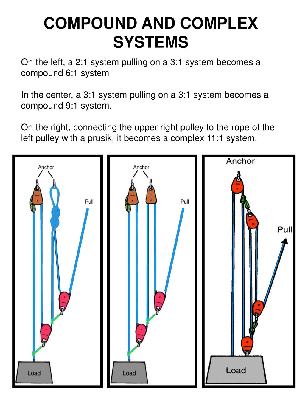
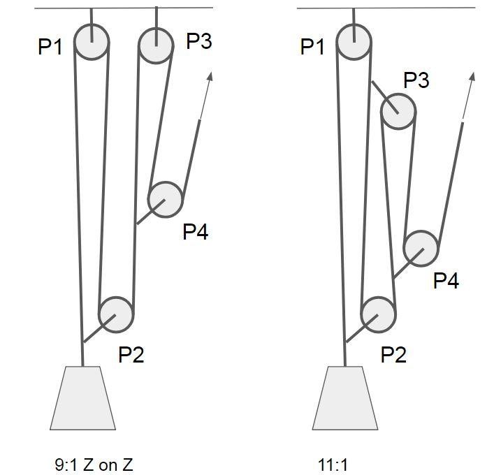
Compound pulley systems are created when a simple pulley system is pulling on another simple pulley system. By adding a 2:1 mechanical advantage to a 3:1 mechanical advantage system you compound, or multiply, the mechanical advantage and end up with a 6:1. A 3:1 pulling on another 3:1 gives you a mechanical advantage of 9:1.
3 to 1 pulley system diagram
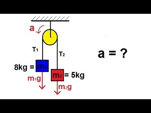
Using the pulley system illustrated to the right below as an example, the basic method for discussed. As in Lessons 15, 16 and 17, the basic method is to draw a free body diagram of the forces involved, write an expression for the net force, and then solve for the acceleration. In a pulley system two masses are strung over a pulley. Note that ... Visit http://ilectureonline.com for more math and science lectures! This lecture series will cover Newton's Second Law of Physics: F=ma. In this video, I wil... and you need to find Pulley 2 size to spin it at 500 RPM, enter Pulley 1 = 6, Pulley 1 RPM = 1000, Pulley 2 RPM = 500, and hit Calculate to find Pulley 2 diameter. Multiple Pulleys - RPM Reduction. To calculate multiple pulley sets, where the first driven (large) pulley shaft drives the second driver (small) pulley, and so on, enter first ...
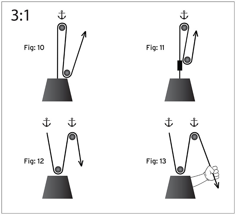
3 to 1 pulley system diagram. If we take a 1:1 system and turn it upside down it will result in a 2:1 mechanical advantage. Instead of the pulley being attached ... Here we have a 3:1 mechanical advantage. First one end of the rope is attached directly to the load, this is then passed around an 3 1 engine diagram pulley system. The procedure is followed on to keep the relative position of pulley 3 constant and string 3 is pulled across a distance of 2 3x x 7x 2 3 1x and finally string x4 which is actually the effort crosses a distance of 2 7x x 15x 2 4 1x meters. 3:1 System The 3:1 is the classic mechanical advantage system used by rescuers. It requires less rope than a (non-piggybacked) 2:1 system, is reasonably easy to rig, is easy to add a progress capture device, provides an appropriate amount of mechanical advantage to raise one or two people, and with a few tweaks it can be converted into a simple 5:1 system . The efficiency (E) of a haul system ... to raise a mass 1 meter with a 3:1 system, 3 m of rope must be pulled. The efficiency (E) of a haul system may be calculated by adding the effects of each pulley. Start by drawing a simple diagram of the system, then show the pulling force ...
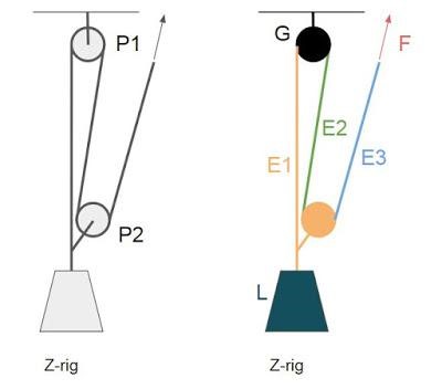
This video demonstrates how to set up a simple 3:1 pulley with a Petzl Reverso. Note that the Reverso acts as a 'progress capturing device' as it allows slac... August 30, 2017 - A few simple pulley systems are most frequently used. The most common is a 3:1 mechanical advantage, sometimes called a “Z” rig because when rigged, the rope looks like a “Z”. In theory, a 100-pound pull would raise a 300-pound load. Due to friction, the actual mechanical advantage ... The 3:1 Pulley System. ropebook 31st July 2019. Here we have a 3:1 mechanical advantage. First one end of the rope is attached directly to the load, this is then passed around an anchored pulley (pulley B) and returns back to the load where it is passed through pulley A which has been fixed to the load. This forms the 3:1 mechanical advantage ... Apr 19, 2015 - Whoa, you’ve rolled right in to the Pulley Systems section! Keep the wheels turning…
The 3:1 Pulley System . Here we have a 3:1 mechanical advantage. First one end of the rope is attached directly to the load, this is then passed around an. Read More » Pulley Systems. The 4:1 Pulley System . This pulley system provides a 4:1 mechanical advantage. The user is required to apply a force of 25kg to raise this 100kg load, for every The 31 pulley system. The following diagrams of 31 simple pulley systems have the pulleys labeled as a and b. Pin On Pulley Systems 21 c pulley crevasse rescue. 3 to 1 pulley system diagram. 31 z pulley diagram. Tacoma branch safety committee. 31 z pulley diagram pdf. Tacoma conservation stewardship committee. Tacoma branch sea kayaking program. Reeving two triple sheave pulleys for mechanical advantage. Therefore the VR of the system can be equated as = Distance Covered by Effort/Distance Covered by Weight = (24 – 1)x/x = 24 – 1, for the present example which consists of 4 pulleys. In general for a particular third system of pulley having n number of pulleys, VR = 2n – 1. MA and ɳ may be taken as discussed for the previous systems.
Frostburg Edu
The efficiency (E) of a haul system indicates the force multiplier factor that you can exert on the rope.For example, if you are able to pull 20 kg maximum on a rope with your bare hands, a 3:1 haul system will enable you to raise a 60 kg mass.This reduction is obtained by increasing the amount of rope to be pulled: to raise a mass 1 meter with ...
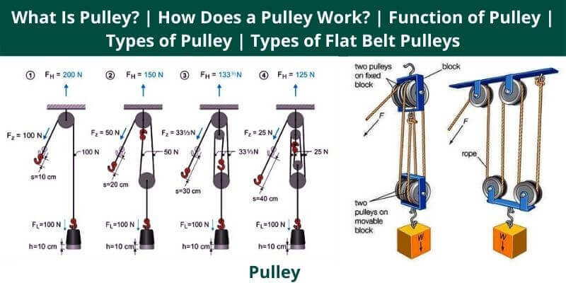
What Is Pulley How Does A Pulley Work Function Of Pulley Types Of Pulley Types Of Flat Belt Pulleys
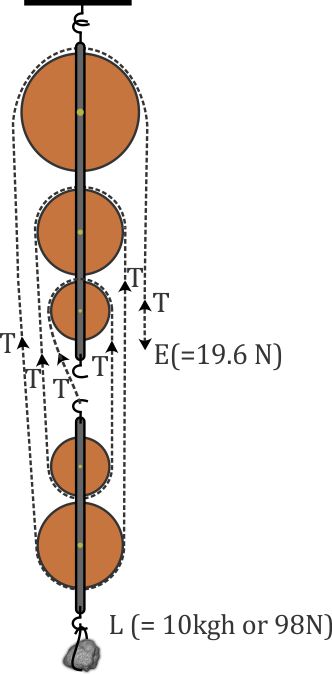
1 Answer1. Show activity on this post. The tension on the rope is everywhere the same and its equal to F. So if you did a free body diagram on the following system by sectioning along the ropes: what you get from the equilibrium is 4 F = 48 [ N].
Ppt East County Fire Rescue Powerpoint Presentation Free Download Id 1454442
Remember that in "odd" numbered systems (e.g., 1:1, 3:1, 5:1, etc) the end of the rope is connected to the load, as shown in this 5:1 system. ... As with this system, complex systems usually have at least one pulley moving in the opposite direction of the load.

Schematic View Of The Main Rope Pulley System For Polar Crane In Npp Download Scientific Diagram
A simple pulley system, where the end of the line is attached to the anchor, has the mechanical advantage, which is equal to 2n where n is the number of moving pulleys. Here F A is the anchor load, F E is the effort force and F L is the load. For example, if there are four moving pulleys and 8 lines (the most left line is used only for change of direction) the MA = 8.

Mechanical Advantage Explained Educated Climber Com
Feb 2, 2016 - Whoa, you’ve rolled right in to the Pulley Systems section! Keep the wheels turning…
Rope Rescue 5 1 System
Attach the fixed pulley to the overhead anchor point, as described in Steps 1 to 3 above. Then, attach the movable bottom pulley directly to the load. Make sure both anchor points are sturdy enough to support to load that will be placed on them. When pulley systems fail, it is almost always at one of these two anchor points.

Pulleys And Mechanical Advantage Systems Cmc Pro
3 to 1 pulley system diagram. The following process may make it easier to remember. The 31 pulley system. Some rescuers find it challenging to remember how to rig a 31 system. The procedure is followed on to keep the relative position of pulley 3 constant and string 3 is pulled across a distance of 2 3x x 7x 2 3 1x and finally string x4 which ...
Rope Rescue 5 1 System
The above system is a 3/1 system pulling on a 3/1 system to create a compound 9/1 mechanical advantage system. The 1T input force runs through the entire first 3/1 system. The first traveling pulley doubles the input force to 2T and adds it to the the 1T force directing that increased force to the second traveling pulley through it's prusik.
Pulley System Analysis Ropelab Online
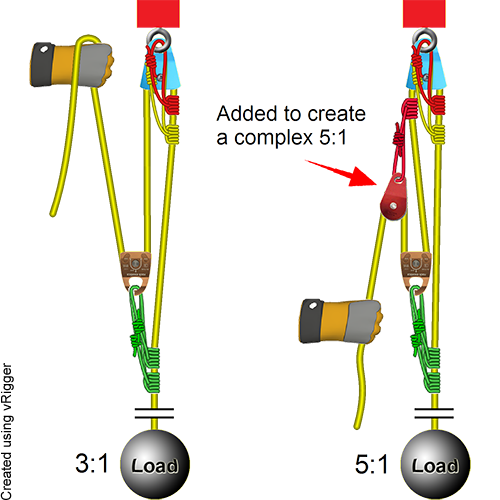
2 - Compound system. When you pull the rope, the pulleys move in the same direction, but at different speeds toward the anchor. This can be created by building a 3:1 Z drag, and then adding a 2:1 onto the strand you're pulling. With a compound system, the mechanical advantage of each separate pulling system is multiplied.
What Is Block And Tackle Pulley System How To Find The Mechanical Advantage And Velocity Ratio Of The System Also How To Find Efficiency Physics Topperlearning Com 2bfp5zrr
If the rope used in the pulley system is tied to the LOAD, the ideal mechanical advantage (IMA) will be ODD (i.e., 1:1, 3:1. 5:1, etc.) Even if a change of direction at the anchor does add friction, it might make your pull easier, depending on your own personal strength, body weight, and the weight of the load you need to move.

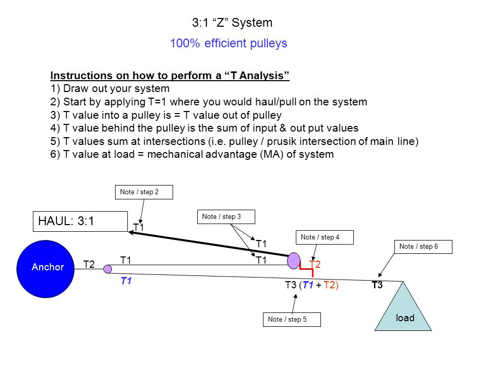
3 1 Z System 100 Efficient Pulleys Instructions On How To Perform A T Analysis 1 Draw Out Your System 2 Start By Applying T 1 Where You Would Haul Pull Ppt Download
This site requires JavaScript · Or you can view the legacy site at legacy.cnx.org/content
Physics Mechanics The Pulley 1 Of 2 Youtube
Here are the step-by-step instructions for reeving your pulleys with this method: Step 1. Lay your two pulleys out in front of you such that the beckets of both pulleys are facing each-other. Lay them about 3 feet from one-another. Step 2. Take one end of your static rope and tie a figure-8 knot on a bite with a Fishermans backup knot.

Types Of Pulley Definition Uses Diagram Examples Advantages Disadvantages Engineering Learn
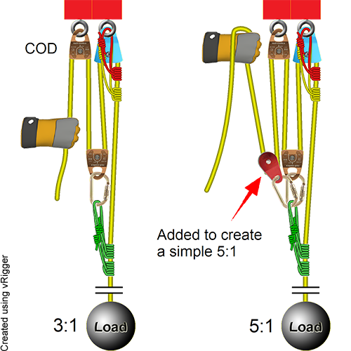
Add a C-Pulley (2:1) to Complete the 6:1 System: To cut in half the force needed to raise the victim on the existing (3:1) pulley system, we only need to add a single pulley to the hauling end. Begin by tying the very end of the remaining rope into the anchor.

Pulley Systems Flaschenzug Pulley Math About Me Mechanical Design
A 3 1 is a go to pulley for low angle rescue or even in your garage. Dont however confuse the 31 with the similarly shaped 21 with a cod pulley or a 21 piggyback system. That image 3 to 1 pulley system diagram fabulous pulley previously mentioned can be labelled with.

Machine Design 101 Pulleys And Counterweights Ie
By adding a pulley to the fixed block of a gun tackle the direction of the pulling force is reversed though the mechanical advantage remains the same, Diagram 3a. This is an example of the Luff tackle. ... The mechanical advantage of a pulley system can be analysed using free body diagrams ...
How To Find The Ideal Mechanical Advantage Of A Pulley Quora
3 to 1 pulley system diagram. 1024 x 768 pixel. 3 to 1 pulley system feb 13 2019. To find out all images in new release pictures of 3 to 1 pulley system diagram graphics gallery please stick to this hyperlink. Dont however confuse the 31 with the similarly shaped 21 with a cod pulley or a 21 piggyback system. Third system of pulleys.
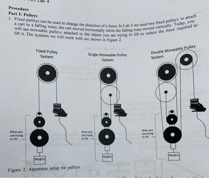
Solved Pre Lab 4 Simple Machines 1 3 Pts Draw A Chegg Com
Diagram 3 shows three rope parts supporting the load W, which means the tension in the rope is W/3. Thus, the mechanical advantage is three-to-one. By adding a pulley to the fixed block of a gun tackle the direction of the pulling force is reversed though the mechanical advantage remains the ...

Enotes Mechanical Engineering
October 24, 2019 - This pulley system provides a 4:1 mechanical advantage. The user is required to apply a force of 25kg to raise this 100kg load, for every…

Simple Machines
3 1 engine diagram pulley system. That image 3 to 1 pulley system diagram fabulous pulley previously mentioned can be labelled with. Dont however confuse the 31 with the similarly shaped 21 with a cod pulley or a 21 piggyback system. The pulley system shown is used to store a bicycle the pulley system shown is used to store a bicycle in a garage.
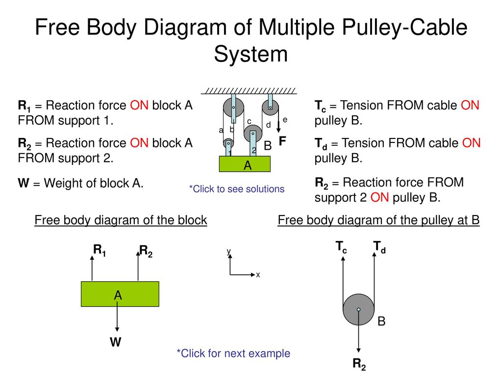
Free Body Diagram Of Cable Pulley System Ppt Download
3 to 1 pulley system diagram. It is obviously beneficial to have a large rigging area to reset the system. Mechanical Systems Mottez bike lift pulley system themottez bike lift pulley system is a pulley system that provides an excellent space saving solution for storing your bike.
Pulley System Analysis Ropelab Online
The diagram below shows a pulley attached to a beam. The rope is 'pulled' on the effort side and the weight being lifted is on the right hand side, called the 'load'. In general a single pulley is useful as it allows the labourer (shown right) to lift the weight without bending his back. This means it is much safer to lift the weight.

How To Calculate First Second And Third Pulley Systems Bright Hub Engineering
31 Aug 2016 — This pulley system provides a 4:1 mechanical advantage. The user is required to apply a force of 25kg to raise this 100kg load, for every…

Patc Ms A More Efficient 3 1 Pulley System
Jul 5, 2021 - Explore Bob DeFoor's board "Pulley systems", followed by 171 people on Pinterest. See more ideas about pulley, block and tackle, pully system.

The Tension In The String In The Pulley System Shown In Img Src Https D10lpgp6xz60nq Cloudfront Net Physics Images Pr Xi V01 C03 E01 195 Q01 Png Width 80
For timing pulleys: For timing pulleys, this is the measurement between the flanges. Belts that fit: The belts, chains, or rope sizes that will fit into the pulley. For V-groove idlers and drives: A belt is considered to fit into a pulley if both the following are true:; The narrowest part of the belt does not touch the bottom of the V-groove.; At least 3/4 of the belt fits inside the groove ...
3 To 1 Pulley System Diagram Wiring Site Resource
4:1 System. Four-to-one systems are less popular than 3:1 systems, probably because they require an additional pulley and don't offer significantly more mechanical advantage. However once you learn how to stack a 2:1 on a 2:1 to create a compound 4:1, you'll know how to stack a 2:1 on a 3:1 to create a 6:1 (also a less-popular system, but worth knowing if you are a rigging geek) and how to ...

3 1 Pulley Systen Setup Or Z Rig Smarter Not Harder Youtube
and you need to find Pulley 2 size to spin it at 500 RPM, enter Pulley 1 = 6, Pulley 1 RPM = 1000, Pulley 2 RPM = 500, and hit Calculate to find Pulley 2 diameter. Multiple Pulleys - RPM Reduction. To calculate multiple pulley sets, where the first driven (large) pulley shaft drives the second driver (small) pulley, and so on, enter first ...
The 2 1 Pulley System Ropebook
Visit http://ilectureonline.com for more math and science lectures! This lecture series will cover Newton's Second Law of Physics: F=ma. In this video, I wil...

Block And Tackle Pulley System Options And Modeling Dlubal Software
Using the pulley system illustrated to the right below as an example, the basic method for discussed. As in Lessons 15, 16 and 17, the basic method is to draw a free body diagram of the forces involved, write an expression for the net force, and then solve for the acceleration. In a pulley system two masses are strung over a pulley. Note that ...

File Four Pulleys Svg Wikipedia
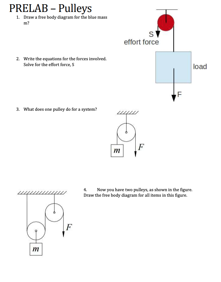
Solved Prelab Pulleys 1 Draw A Free Body Diagram For The Chegg Com

A Pulley With A Radius Of 3 0cm And A Rotational Inertia Of 4 5x10 3kg M 2 Is Suspended Form The Ceiling A Rope Passes Over It With A 2 0kg Block Attached To One End

M 4 Pulley Systems

Overview Of A Simple Pulley System Alpine Savvy
Dmm Professional Resistance Is Futile
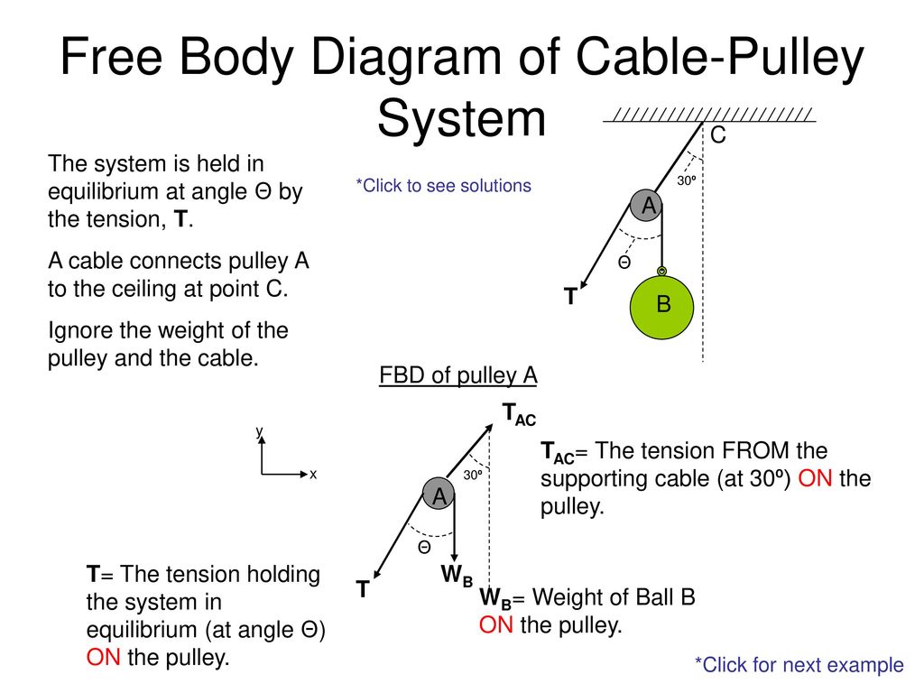
Free Body Diagram Of Cable Pulley System Ppt Download
Rope Rescue 3 1 System
Degrees Of Freedom For Complex Pulley Systems Engineering Stack Exchange
How Is A Pulley S Mechanical Advantage Determined Quora

Diagram Of A Pulley System With Arrows Download Scientific Diagram

Pulleys Physics For K 12 Openstax Cnx
0 Response to "40 3 to 1 pulley system diagram"
Post a Comment