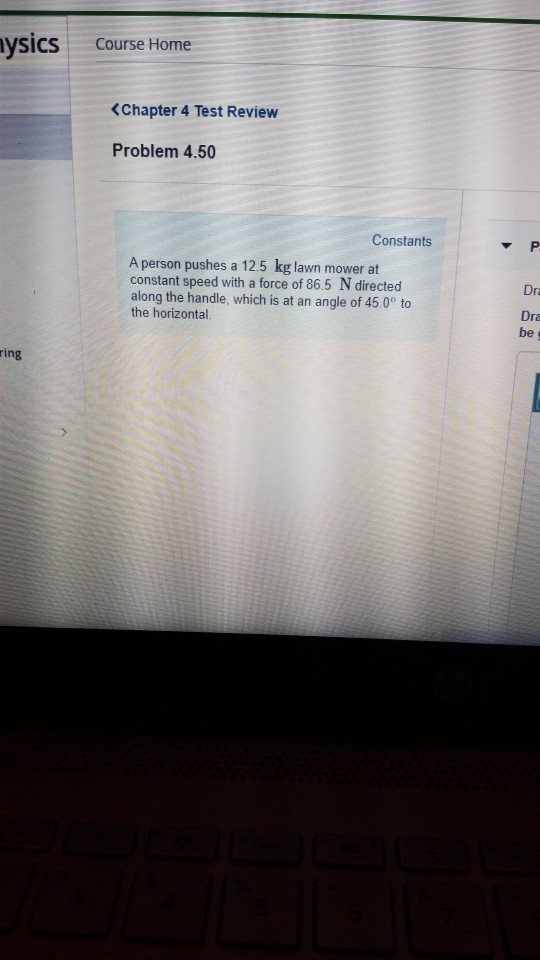
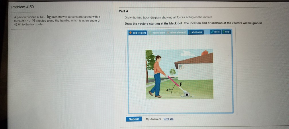
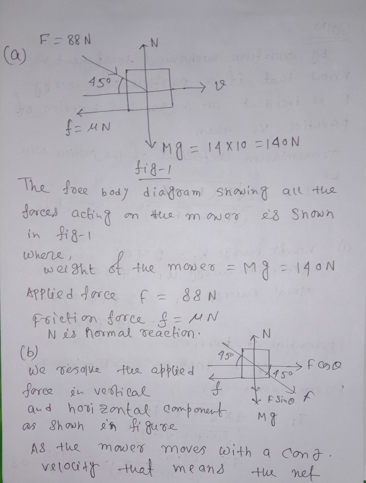
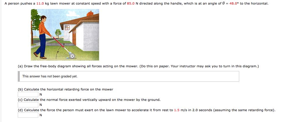
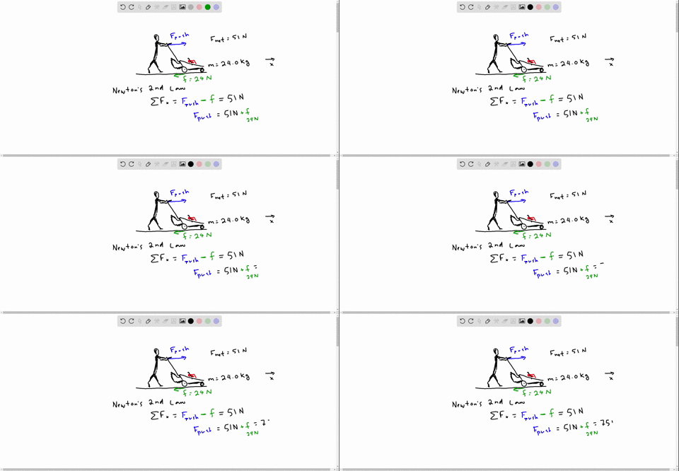
40 draw the free-body diagram showing all forces acting on the mower.
applied force : A force that gives the rocket forward acceleration (usually a rocket booster). Thrust is an example. free-body diagram: A diagram that shows all the forces acting upon an object. Newton's first law : If the forces are balanced, the body will stay at rest or continue with the same velocity, neither accelerating nor decelerating ... The unit vectors i, j, and k act in the x-, y-, and z-directions respectively. So in our diagram, since we have a unit cube, OA = i OC = j OS = k . From the diagram, we see that to move from B to S, we need to go −1 unit in the x direction, −1 unit in the y-direction and up 1 unit in the z-direction. Since we have a unit cube, we can write:
Draw Stress Strain Diagram For Mild Steel Rod And Show. ... Free body diagrams are drawings that help scientists sort out what forces are acting on an object. For simplicity, the object is always draw... 42 Savage Model 29 Parts Diagram.
Draw the free-body diagram showing all forces acting on the mower.
An OER from Textbook Equity · 2014 · ScienceIn Figure 4.7, the net external force on the 24-kg mower is stated to be 51 N. ... Vol 1 of 3 free-body diagram, including all forces acting on the system. Free-body diagrams have been used in examples throughout this chapter. Remember that a free-body diagram must only include the external forces acting on the body of interest. Once we have drawn an accurate free-body diagram, we can apply Newton's first law if the body is in equilibrium (balanced forces; that is, ) or Newton's second law if the ... F12 = F32 = 108 N. T = − F32 × h = −108 × 180 = −19440 N mm (cw) Fig. 11.11 Static force analysis of four-bar mechanism. Torque exerted by the crank shaft on link 2, T2 = − T = 19440 N mm (ccw) Now complete the force polygon for all the forces acting on the mechanism, as shown in Fig.11.11 (d). F14 = 52.5 N.
Draw the free-body diagram showing all forces acting on the mower.. Concept of drawing all forces acting on control volume seems to have no sense in fluids because control volume doesn't move in space and time like solid body does. It's center of mass doesn't move in space and time like in solid bodies, but rather fluid has different velocity on different cross sections or points in the pipe. Part A Draw the free-body diagram showing all forces acting on the mower. Draw the vectors starting at the black dot. The location and orientation of the ... ... to the horizontal Draw the free.body diagram showing all forces acting on the mower Draw the ... Calculate the horizontal friction force on the mower. Question: Draw the free-body diagram showing all forces acting on the mower. Draw the vectors starting at the black dot. The location and orientation of the ...
(a) Draw a free body diagram showing all forces acting on the mower. (b) Calculate the horizontal friction force on the mower, the normal force exerted ...1 answer · Top answer: GIVIEN: • m=14 kgm=14 kg is the mass of the mower • F=88 NF=88 N is the force applied • θ=45∘θ=45∘ is the angle... your body. Paul goldman what do anthropologist margaret mead, pro golfer duffy waldorf, actress whoopi goldberg, basketball player julius erving and first prim. Active range of motion exercises for your shoulder and rotator cuff can help improve mobility around your shoulder and rotator cuff. He served as assistant team physician to chi. $10 tier on Patreon you can immediately unlock all solutions. 9.1 - Draw the shear force and bending moment diagram of this simply supported beam with a single applied point load at mid span. Solution. Physics Statics Problems And Solutions Merely said, the physics statics problems and solutions is universally compatible as soon as any devices ... We use free-body diagrams to show the different directions and magnitudes of the forces that act on a body. In equilibrium, these forces should all equate to zero. Considering all upward forces as positive and downwards as negative, our equation is: ΣF↑ = 0 = T + (-W) T = W where weight, W, becomes negative since it is directed downwards.
Draw a free body diagram, looking down on the plane, showing clearly the forces which act on the block in. Draw a free body diagram, looking down on the plane, showing clearly the forces which act on the block in the horizontal direction. Categories Uncategorized. Leave a Reply Cancel reply. (a) Draw the free-body diagram showing all forces acting on the mower. Calculate (b) the horizontal friction force on the mower, then (c) the normal force ...5 pages Your scanned work should include a free body diagram showing all forces acting on the object(s), as well as a step-by-step solution to the problem and upload your responses to the same W2 Assignment 2 Dropbox. Question 1 . A 2 kg book resting on a flat table requires an applied force of 4 N to make it move. Your scanned work should include a free body diagram showing all forces acting on the object(s), as well as a step-by-step solution to the problem. Question 1 A 2 kg book resting on a flat table requires an applied force of 4 N to make it move.
13:43(a) Draw the FBD showing all forces acting on the mower. (b) Calculate the horizontal friction force on the ...5 May 2017 · Uploaded by Physics In The Flesh
1.Draw Free-Body Diagram 2.Defined Coordinate System 3.Label All Forces 4.Apply Newtons 2nd law 5.Use uniform Circular motion 6.Solve for Tangential Velocity tano-us Note: if pls > tand then Vmin = 0 Vmin gr 1+Mstano tano+lis Vmax Vgr and if Mstand > 1 then there is no Vmax 1-Mstand Example: If a curve with a radius of 50.0 meters is banked at ...
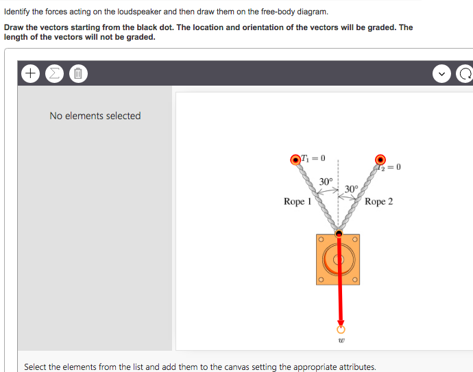
Identify The Forces Acting On The Loudspeaker And Then Draw Them On The Free Body Diagram Wiring Site Resource
Figure 5.32 (a) The free-body diagram for isolated object A. (b) The free-body diagram for isolated object B. Comparing the two drawings, we see that friction acts in the opposite direction in the two figures. Because object A experiences a force that tends to pull it to the right, friction must act to the left. Because object B experiences a component of its weight that pulls it to the left ...

Openstax College Physics Solution Chapter 4 Problem 5 Problems Exercises Openstax College Physics Answers
- Draw free body diagrams of all components. - Show forces, moments and toques (if any) acting on each component. - Identify critical points based on stress analysis. - Use a factor of safety between 1.5 and 2 to size each component. - Determine the factor of safety for fatigue failure of each component.
There are three equivalent ways to determine this torque, as shown in the diagram below. Method 1 - In method one, simply measure r from the hinge along the rod to where the force is applied, multiply by the force, and then multiply by the sine of the angle between the rod (the line you measure r along) and the force.
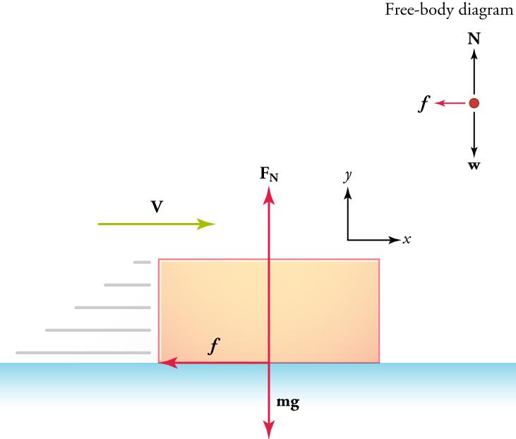
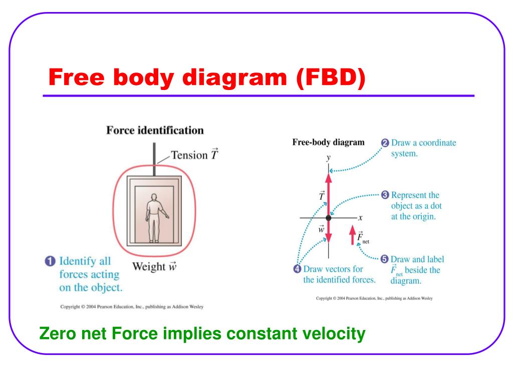
A free body diagram is a representation of an object with all the forces that act on it. We use these free body diagrams in applications of newtons laws. Be sure to consider newtons third law at the interface where the two blocks touch. Draw the force vectors such that their tails align with the center of the block indicated by the black dot.
A free-body diagram is a picture or sketch used by physicists and engineers to show the forces acting on an object, with arrows representing forces. The longer the arrow, the stronger the force. A ...
Question: your diagram? 4. An escalator is 30.0 meters long and slants 30 degrees relative to the horizontal. If it moves at 1.00 m/s, at what rate does it do work in lifting a 50.0 kg man from the bottom to the top of the escalator? T y 20 Did you draw free-body diagram for this problem? If so, why did you draw a diagram?
Transcribed image text: 4.50 Draw the free-body diagram showing all forces acting on the mower Calculate the horizontal fricton force on mower.
Using Free Body Diagram Show That It Is Easy To Pull An Object Than To Push It Using Free Body Diagram Sarthaks Econnect Largest Online Education Community
The formula for calculating net force is the mass of the object multiplied by the acceleration. If the net force acting on an object is zero, then it means that the object's velocity is constant and the object isn't speeding up or slowing if the net force acting on an object is zero, then it means that the object's velocity is constan.
(ii) bending moment diagram showing the shape . Beam subjected to a concentrated load as shown in the figure. Draw the shear and moment diagrams for the beam shown below along with the supporting equations v(x) and m(x), and determine the . Draw the free body diagram for the beam. Also, draw the shear force diagram (sfd) .
On the worksheet, students analyze forces acting on a car-object system; see Figure 3. Note that the system is in equilibrium, that is, the green block is assumed to be heavy such that a car cannot move it from its position (also see slide #4). Figure 3. An illustration of a car pulling on a heavy object and its corresponding free body diagram.
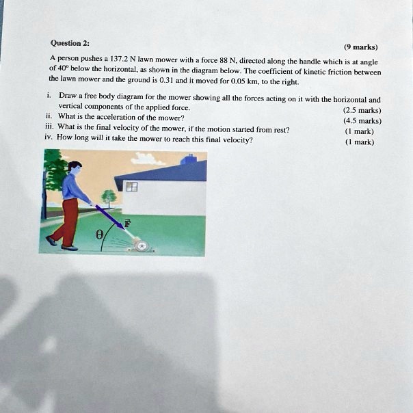
Solved Question Marks Person Pushes 137 2 Lawn Mower With Force Directed Along The Handle Which Anglc 40 Helow The Horizontal 45 Shown Thc Diagram Below The Coefficient Of Kinetic Friction
A force has both magnitude size and direction. The shear force between point A and B is usually plotted on a shear force diagram. A free-body diagram is a drawing of all external forces acting on a body. Force Field Analysis is an analytical technique used to determine the driving and restraining forces affecting the chief problem or question.
Light Reactions of Photosynthesis light is captured in photosystems that contain antenna complexes and a reaction center there are two types, Photosystem I and Photosystem II antenna complexes are highly organized arrangements of pigments, proteins, and other molecules that capture light energy energy is transferred to a reaction center Photosynthesis Light Reaction Diagram. the process of ...
... which is at an angle of θ = 48.0° to the horizontal (a) Draw the free-body diagram showing all forces acting on the mower. (Do this on paper.
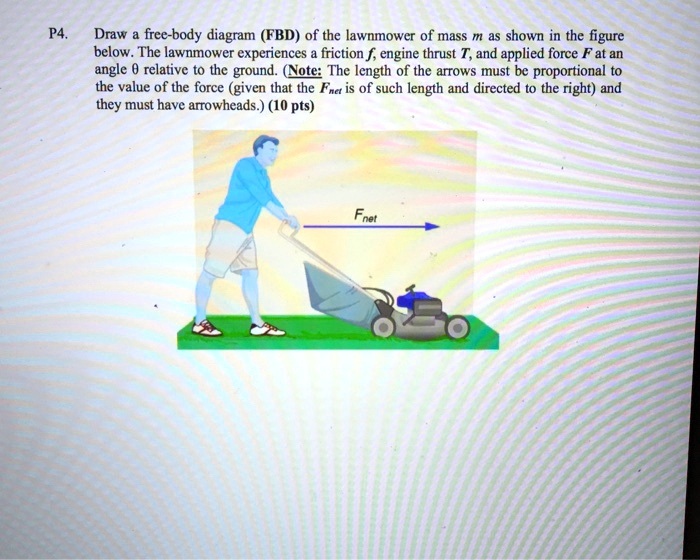
Solved P4 Drw Free Body Diagram Fbd Of The Lawnmower Of Mass M As Shown In The Figure Below The Lawnmower Experiences Friction F Engine Thrust And Applied Force F At An Angle Relative
F12 = F32 = 108 N. T = − F32 × h = −108 × 180 = −19440 N mm (cw) Fig. 11.11 Static force analysis of four-bar mechanism. Torque exerted by the crank shaft on link 2, T2 = − T = 19440 N mm (ccw) Now complete the force polygon for all the forces acting on the mechanism, as shown in Fig.11.11 (d). F14 = 52.5 N.
Free-body diagrams have been used in examples throughout this chapter. Remember that a free-body diagram must only include the external forces acting on the body of interest. Once we have drawn an accurate free-body diagram, we can apply Newton's first law if the body is in equilibrium (balanced forces; that is, ) or Newton's second law if the ...
An OER from Textbook Equity · 2014 · ScienceIn Figure 4.7, the net external force on the 24-kg mower is stated to be 51 N. ... Vol 1 of 3 free-body diagram, including all forces acting on the system.

Draw The Free Body Diagram Showing All The Forces Acting On The Box Draw The Vectors Starting Homeworklib
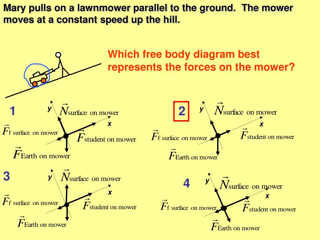
Ppt Which Free Body Diagram Best Represents The Forces On The Mower Powerpoint Presentation Id 3093881


.PNG)

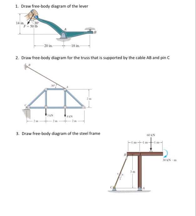





0 Response to "40 draw the free-body diagram showing all forces acting on the mower."
Post a Comment