44 disconnect switch wiring diagram
The Complete Guide to Electrical Wiring. Angky Tri Aditya. Download Download PDF. Full PDF Package Download Full PDF Package. This Paper. A short summary of this paper. Most symbols used on a wiring diagram look like abstract versions of the real objects they represent. For example, a switch will be a break in the line with a line at an angle to the wire, much like a light switch you can flip on and off.
Residual-current and over-current protection may be combined in one device for installation into the service panel; this device is known as a GFCI (ground fault circuit interrupter) breaker in the US and Canada, and as a RCBO (residual-current circuit breaker with over-current protection) in Europe and Australia.
Disconnect switch wiring diagram
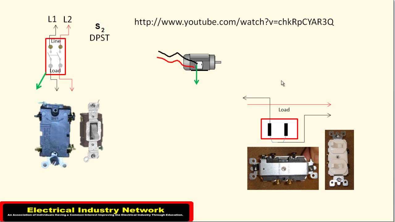
Wiring diagram of a DPDT connected motor plus two snap-action switches for user control with limit stops. The wiring diagram above is similar to the ones shown earlier. Two additional switches have been inserted. One switch connects (or disconnects) the white wire on the bottom terminal. In today basic electrical wiring installation tutorial, we will discuss step by step method of staircase wiring installation by using 2-way switches (SPDT = Single Pole Double Through Switch). Also, the same wiring circuit diagram can be used for 2-way lighting or controlling electrical appliances from two different places by using two-way switches. Harness Wiring. Note: This is a general wiring diagram for automotive applications. ... Disconnect the battery. Scotch-lock the bare end of the GREEN wire to the low or high beam lead. Connect the other end of the GREEN wire to the green switch wire terminal.
Disconnect switch wiring diagram. Cut the hot wire(s). If your switch designates a connector for the supply side, hook the wire coming from the circuit breaker or power meter here. The other ... 21-07-2017 · The old zing ear switch I am replacing is a SHINE TOP LS-102 6A125VAC 3A250VAC E218558. The current wiring for the old switch are as follows: L orange wire, 2 purple wire, 3 black wire, and 1 yellow wire. I connected the wires to the new zing ear model number ZE-268s6 as follows: L orange wire, 2 purple wire, 3 black wire, and 1 yellow wire. Related Post: How to Connect a Portable Generator to the Home Supply – 4 Methods Below is a given UPS Inverter connection and wiring diagram to the home supply. The circuit shows that only two rooms of the home are depends on the UPS and Batteries as well as main supply to maintain the uninterruptible power to the connected appliances and load such as lighting points and fans etc and the ... Caution: To prevent severe shock or electrocution always turn the power OFF at the service panel before working with wiring. Never Assume the power is off!
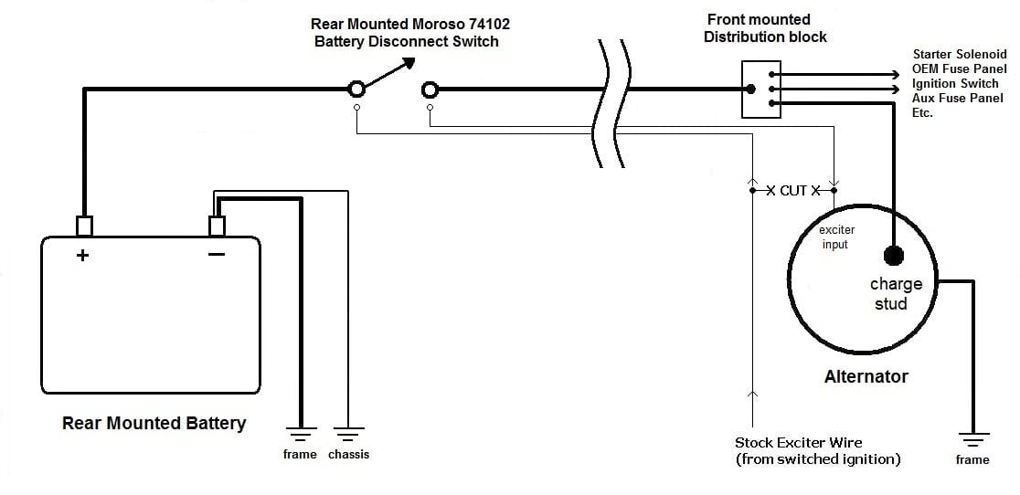
5 Mar 2021 — If you store your car any length of time, then a dead battery is a real possibility. The easy solution is installing a battery disconnect ... HOW TO: Wire a DPDT Rocker Switch for Reversing Polarity: When you need to control a DC motor (such as a DC linear actuator) you usually need to be able to swap the polarity on the wires going to the motor. A double pole, double throw switch is used for this purpose but you have to wire it up correctly t… 9 Jun 2021 — The main disconnect is required on all household wiring systems. Learn the basics of a standard disconnect switch housed in its exterior ... Apply the On/Off label. WIRING. 1. Disconnect the positive and negative battery terminals. 2. Once the switch has been mounted, ...2 pages
But, can't find a single wiring diagram/picture/FAQ for hondas (even though it's the same, i don't wanna FUBAR it). So, here's what I have: - Longacre 4 pole (2 ... Dec 04, 2020 · This DIY camper solar wiring diagram and parts list is perfect for ground-up electrical installs into campervans, skoolies, or expedition vehicles. This system is most suitable for systems that do not have a pre-existing house electrical system installed. This diagram features: 2000W Inverter Charger; 200+ Amp Hours of Battery Storage Capacity 5 steps · 10 hrs · Materials: AC Disconnect switch, Screwdriver, Drill, Drill bits, Screws ...1.The disconnect switch should be screwed into place on the wall next to the AC unit. Depending on where the cables will be inserted into the switch box, the proper knock-out plugs can be removed once you've mounted the switch, and cable connectors can be fastened into place.If the disconnect is added to an existing AC Unit, it should be within reach of the already existing cable, so only a short cable is needed to bridge the switch to the AC unit.2.With the breaker turned OFF, the wires can be disconnected and the cable removed from the electrical compartment of the AC Unit.For a new AC installation, a cable must be installed from the disconnect to reach up to the main electric panel. A hole must be drilled through the wall to bring the cable inside. It’s a good practice to pre-drill a smaller hole with a long drill bit to make sure it’s where it should be and avoid unpleasant surprises. The hole can then be drilled VW Car Manuals PDF & Wiring Diagrams, Volkswagen Fault Codes DTC above the page - 1500, 1500S, Amarok, Beetle, Bora, CC, Crafter, Eos, Golf, Jetta, Kafer, Karmann Ghia, Lupo, Passat, Polo, Scirocco, Sharan, Tiguan, Touareg, Transporter; VW EWDs. In 1937, Volkswagen was founded, which was to become the symbol of the new Germany. In the shortest possible time, an ultramodern factory was …
Exciter Disconnect Harness Kit Ce Auto Electric Supply
2. For safety reasons, disconnect the motor from the battery or batteries when the motor is not in use or while the battery/batteries are being charged. 3. Improper wiring of 24/36/48-volt systems could cause battery explosion! 4. Keep wire wing nut connections tight and solid to battery terminals. 5. Install battery in a ventilated compartment.
Service Disconnect Wiring Diy Home Improvement Forum
We will now go over the wiring diagram of a SPDT Toggle Switch. Below is the schematic diagram of the wiring for connecting a SPDT toggle switch: SPDT Toggle Switch. A SPDT toggle switch has 3 terminals. Terminal 1 can connect up to any load to power a certain device. And terminal 3 can connect to any load to power any device.

Fastronix High Current Double Pole 4 Post Master Battery Disconnect Switch With Face Plate In Kenya Whizz Battery Switches
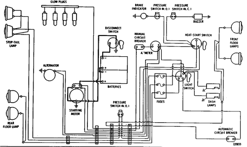
Find out how to access AutoZone's Wiring Diagrams Repair Guide for GM Full-Size Trucks 1988-1998 . AutoZone's Repair Guides tell you what you need to know to do the job right.

Kib Lr9806 Battery Disconnect Latching Relay
24 Apr 2019 — Usually, I see battery disconnect switches wired in on the positive side of the battery. Here is a simple wiring diagram I found on Google.Battery Disconnect Wired Wrong from Factory? - Jayco ...28 Jul 2018Battery disconnect switch doesn't disconnect anything - Jayco ...5 Dec 2017More results from www.jaycoowners.com

How To Wire Safety Switch
Battery Switch Wiring Diagrams Single Engine, Single Battery Diagram. Single Engine, Two Batteries. Switch Position indicates which battery (#1, All, #2) ... The Perko Single Battery Disconnect Switch permits the battery to be shut off from the electrical system when the vessel is not in use.
Wiring Diagram 7k9637 N S 24 Volt System Effective With Serial No 41j919 920 Wheel Loader Avspare Com
The selector switch disconnects the holding circuit contact and jogging may be accomplished by pressing the. Start push button.109 pages
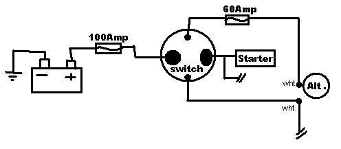
Help Wiring My 4 Pole Battery Disconnect Switch Honda Tech Honda Forum Discussion
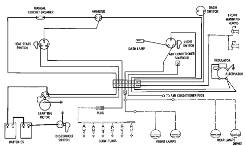
Harness Wiring. Note: This is a general wiring diagram for automotive applications. ... Disconnect the battery. Scotch-lock the bare end of the GREEN wire to the low or high beam lead. Connect the other end of the GREEN wire to the green switch wire terminal.
Wiring Diagram For A Battery Disconnect Ls1tech Camaro And Firebird Forum Discussion
In today basic electrical wiring installation tutorial, we will discuss step by step method of staircase wiring installation by using 2-way switches (SPDT = Single Pole Double Through Switch). Also, the same wiring circuit diagram can be used for 2-way lighting or controlling electrical appliances from two different places by using two-way switches.

1 Example Of A Pv Array Wiring Diagram Showing Disconnect Locations Download Scientific Diagram
Wiring diagram of a DPDT connected motor plus two snap-action switches for user control with limit stops. The wiring diagram above is similar to the ones shown earlier. Two additional switches have been inserted. One switch connects (or disconnects) the white wire on the bottom terminal.

How To Wire A Well Pump To The House Kobo Guide

3 Phase Disconnect Youtube

Buy Ktnnkg Remote Battery Disconnect Switch Auto On Off Kill Switch For Car Dc12v 180a Silver Contact Electromagnetic Solenoid Valve Terminal Online In Indonesia B07dfm2nj3
Hooking Up Battery Disconnect Switch For Street Use Honda D Series Forum
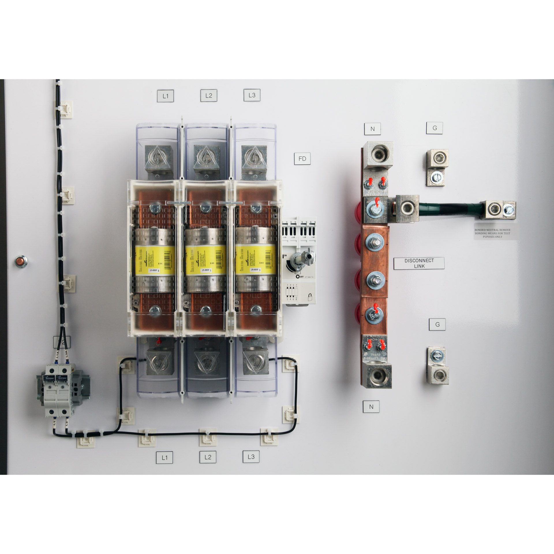
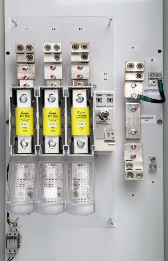
Fused Disconnect Switch Safety Switches Psi Control Solutions

New Bmw E46 M43 Wiring Diagram Diagram Diagramtemplate Diagramsample Electrical Wiring Diagram Wire Boat Wiring
250 Volt Swimming Pool Disconnect Switch Youtube

Buy Nstart Boat Battery Cut Shut Off Kill Switch 12v 48v Marine Battery Disconnect Switch Waterproof Master Power Dual Battery Isolator Switch 300 1000 Amp For Car Small Yacht Rv Camper Truck Vehicle Online In Indonesia B07x7hk2c6

How To Wire Safety Switch
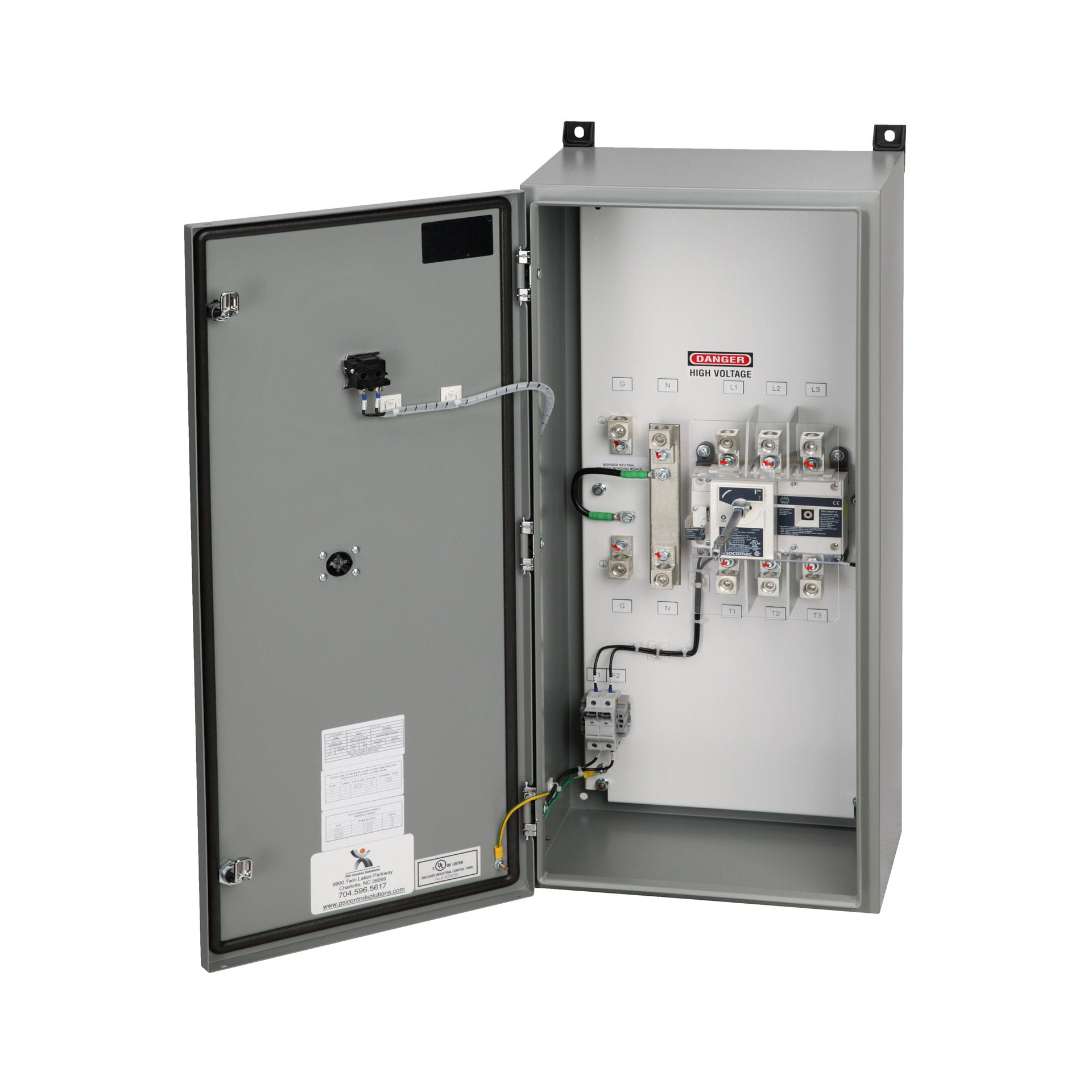
Safety Switches Disconnect Switches Psi Control Solutions

Full Wiring Diagram Unduh Apk Versi Terbaru 1 0 Com Full Wiring Diagram Electricals Car Book

Battery And Wiring 3y5781 N S Wiring Diagram Effective With Serial No 65v2944 65v3400 D7g Track Type Tractor Avspare Com

Solved In The Conduit Layout Shown In Figure 18 6 Determine How Many 1 Answer Transtutors

Vrv Or Vrf Electrical Connection Hermawan S Blog Refrigeration And Air Conditioning Systems

Wiring Diagram 3a1459 N S 24 Volt System Serial No 59j1 To 59j1077 Inclusive D4d Track Type Tractor Avspare Com

Instructions
Wiring For Battery Disconnect Ls1gto Forums

How To Wire Safety Switch
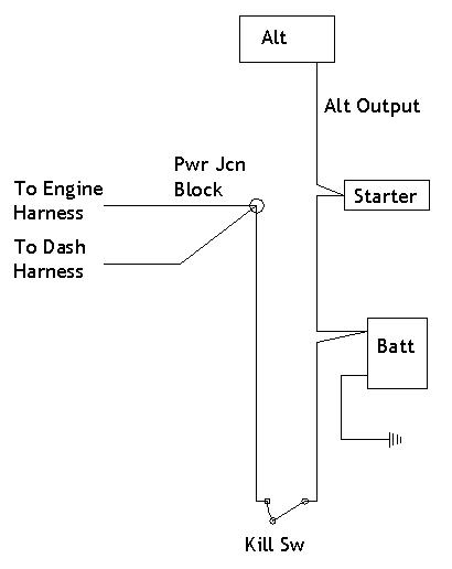
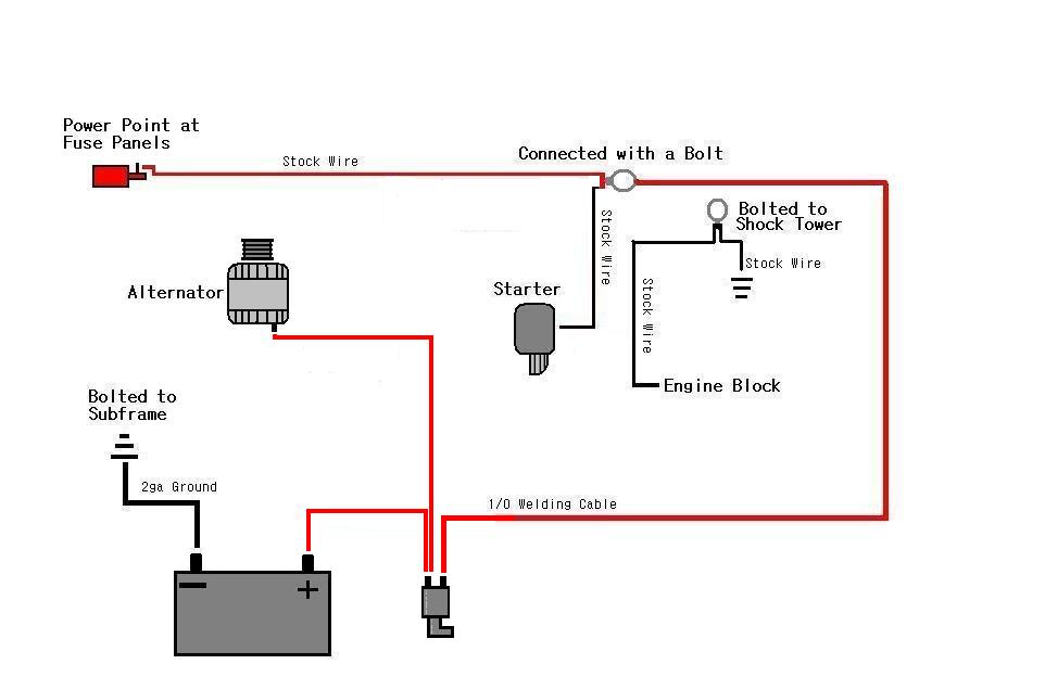
Alternator With Battery Disconnect Ls1tech Camaro And Firebird Forum Discussion

Battery Disconnect Kill Switch Miata Turbo Forum Boost Cars Acquire Cats
Three Auxiliary Contact 30 Amp Unfused Disconnect

Electrical Engineering World Wiring Diagram For This Mobile Off Grid Solar Power System
Trunk Mounted Battery Disconnect Switch Njfboa Home Of New Jersey S Camaros And Firebirds

Diagram Database Free Read Or Download Diagram Database

Ladder Diagram Basics 3 2 Wire 3 Wire Motor Control Circuit Youtube
Safety Switches Disconnect Switches Psi Control Solutions

Wiring Diagram For 220 Volt Air Compressor Http Bookingritzcarlton Info Wiring Diagram For 220 Vol Well Pump Pressure Switch Submersible Well Pump Well Pump

Battery Disconnect Switch Doesn T Irv2 Forums
Wiring Diagram 24 Volt System D8k Track Type Tractor Avspare Com

Single Phase 240 V Motor Controlled By Transformer And Disconnect Switch Circuit Breaker Electrical Engineering Pics

12v Battery Isolator Disconnect Cut Off Power Kill Switch For Car Truck Boat Atv Buy 12v Battery Isolator Disconnect Cut Off Power Kill Switch For Car Truck Boat Atv In Tashkent

How To Wire Safety Switch

Safety Disconnect Switch Wiring Doityourself Com Community Forums
3

Buy Nilight 1 2 Both Off Battery Switch 12v 48v Battery Disconnect Master Cutoff Switch For Marine Boat Car Rv Atv Utv Vehicle Waterproof Heavy Duty Battery Isolator Switch 90108a Online In Indonesia B0896ztzlh
0 Response to "44 disconnect switch wiring diagram"
Post a Comment