45 5 wire door lock diagram
Here is an easy 5 wire setup for anyone to use in any vehicle without the use of any relays Description : Power Door Locks & Wiring Diagram - Youtube inside Ford Transit Central Locking Wiring Diagram, image size 480 X 360 px. Truly, we have been remarked that ford transit central locking wiring diagram is being one of the most popular subject at this moment. So we attempted to uncover some great ford transit central locking wiring ...
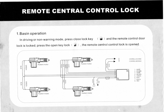
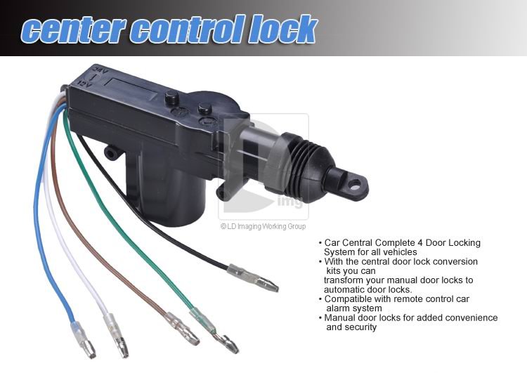
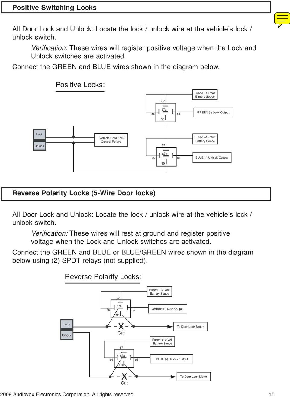
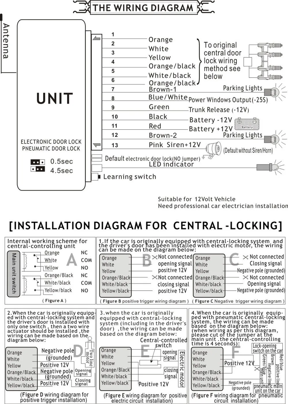
3. Cut the drivers door lock wire. This wire will have 12 volts when lock button is pushed. 4. Connect the ORANGE/BLUE wire to the switche's side of the lock wire. 5. Connect the BLUE/WHITE wire to the motor's side of the lock wire. 6. Cut the drivers unlock wire. This wire will have 12 volts when unlock button is pushed. 7.
5 wire door lock diagram
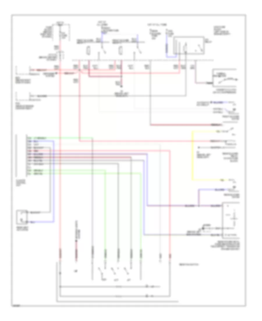
From the thousands of photographs on the net about door lock actuator wiring diagram, we all choices the very best collections with best resolution just for you all, and this photographs is actually considered one of photos collections in this very best pictures gallery concerning Door Lock Actuator Wiring Diagram.I hope you will as it. This kind of impression (Aftermarket Door Lock Actuator ... These GM wiring diagrams provide schematics for vehicle model years 1988 through 1998. Access our free Wiring Diagrams Repair Guide for GM Full-Size Trucks 1988-1998 through AutoZone Rewards. These diagrams include: Fig. 1: Index of Wiring Diagrams. Fig. 2: Sample Diagram: How to Read and Interpret Wiring Diagrams. Fig. 3: Wiring Diagram Symbols. When the switch is closed, the green/white wire sends a signal to terminal 6 of the PSE, either from Green/red, or ground (brown). The PSE either sends vacuum or pressure to the door lock actuator. The green/red gets power from F4f11, so fuse 11 in the rear fuse box. Other wires at the switch are only for lighting.
5 wire door lock diagram. 5 Wire Door Lock Actuator Wiring Diagram - wiring diagram is a simplified pleasing pictorial representation of an electrical circuit. It shows the components of the circuit as simplified shapes, and the power and signal associates in the company of the devices. A wiring diagram usually gives suggestion not quite the relative viewpoint and ... December 23, 2018. 5 Wire Actuator Diagram . Actuator spring door actuator wiring 5 wire central locking actuator wiring diagram simple servo type direct acting diagrm pneumatic cylinder diagram pneumatic actuator diagram double acting actuator cutaway diagram 5 wire door lock actuator diagram 17.vancouvervisions.com. Door Locks - 5 Wire Alternating 12 Volts Positive (Type C) Relay Wiring Diagram. The switch, when moved in either direction, applies both power and ground directly to motor legs without the use of any relays. Except, at the switch in this case, both motor legs rest at ground . Therefore it is only necessary to change the polarity of one motor ... 5 - WIRING INSTRUCTIONS— magnetic lock or fail safe strike with button, keypad, PIR and touch sense bar or micro-switch bar wired in series N/C PIR Power Supply for fail safe strikes and magnetic locks should be DC. If this is not available you may use an AC power source an d wire inline a "Full Wave Bridge" rectifier.
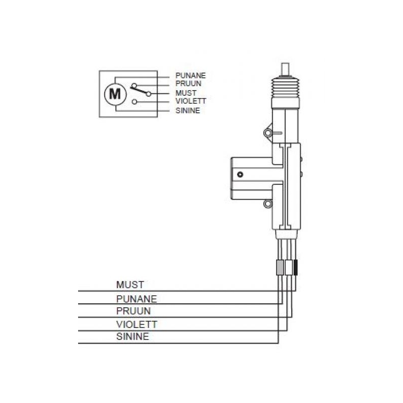
EXTRA INFORMATION: NOTE #1: Vehicles WITHOUT a FACTORY KEYLESS use a TYPE C Door Locking System and Vehicles WITH a FACTORY KEYLESS use a Chrysler 3/5 Wire Door Lock System, to connect, See DIAGRAM....."EXTRA NOTE".... on some KEYLESS ENTRY SYSTEMS, look for a ORANGE/BLACK and a PINK/BLACK these wires may work as a TYPE A Door Locking system. system. Make sure to mark which wire is lock and unlock. "Type B" Door Lock Test (Most Imports, some newer Fords) Probe both door lock wires going to the door lock switch these wires are usually located in the driver's kick panel. Attach one end of your test light to +12V using the vehicle's door lock controls activate Dec 27, 2020 - 5 Wire Door Lock Actuator Wiring Diagram Wire Center Best Of Power There are 5-wire motors and 2-wire motors. The 5-wire version is used indoors that have a key-lock. There are 2 connections for the motor itself and 3 connections for the sensor part (an 'open' and a 'close' contact). These sensors determine whether the door is to be unlocked or locked. If there is no key lock in the door, these sensors ...
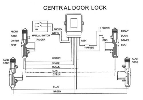
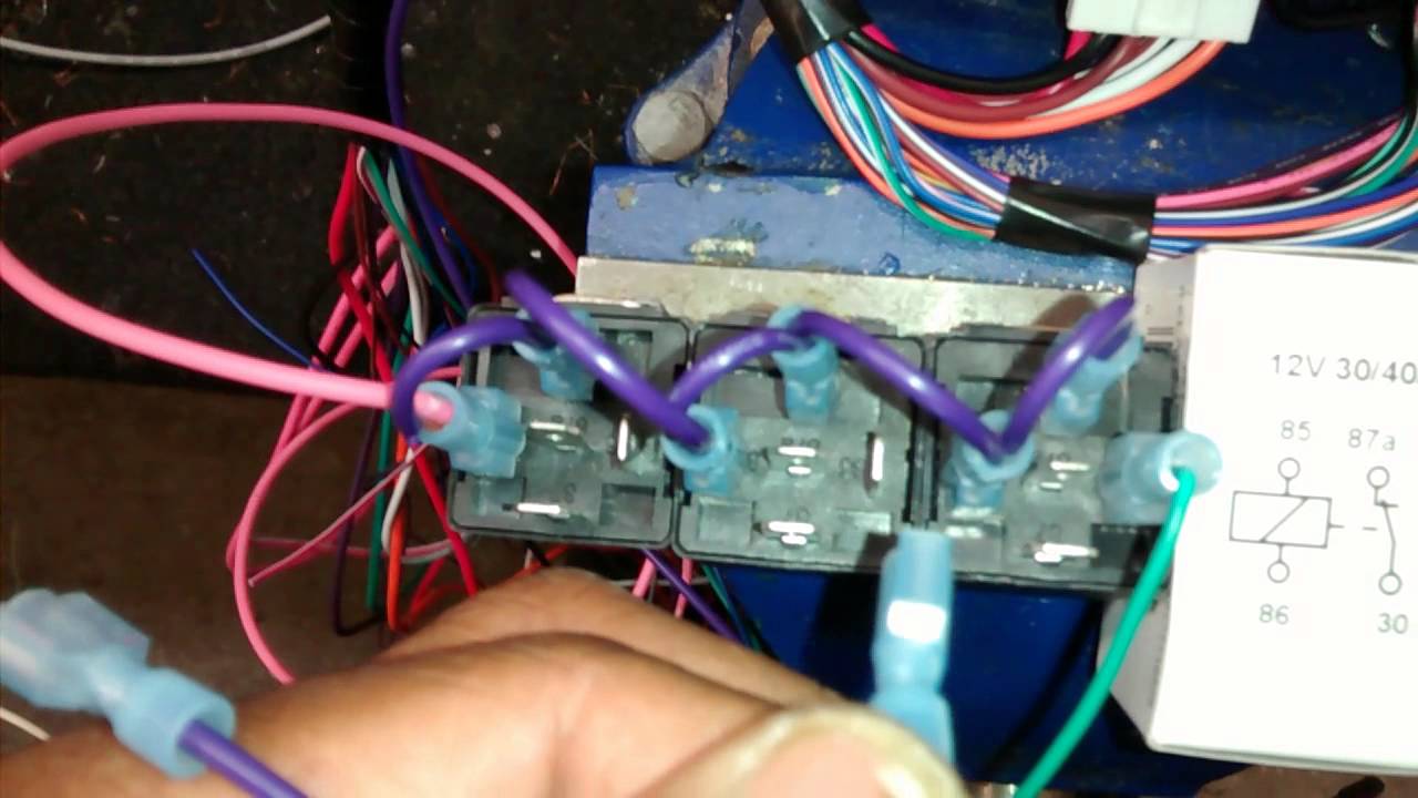
How to Wire Automotive SPDT Relays. Door Locks - 5 Wire Alternating 12 Volts Positive (Type C). The switch, when moved in either direction, applies both power and ground directly to motor legs without the use of any relays. Except, at the switch in this case, both motor legs rest at ground . Theref WIRING DIAGRAMS 1 2 TECH SUPPORT HOTLINE: 503.693.1918 ... Repeat steps 1-10 for each door. WIRING 1. Run all the wires to the location of the door lock module. Be sure to ... factory door lock rod using the screws given (Figure 2). You can mount the actuator directly to the door, or use the bracket to cross a part of the ... if you are doing a conversion from non power to power locks use the 5 wire to control the other locks. green lock, blue unlock. wire up the relays like your diagram and run it to the blue and green wire on the actuator. the actuator on the passenger door cut off the white brown and black wire and on the driver door ground the black wire and tie in the white and brown wire on the blue and green ... 5 Wire Alternating 12 Volts Positive Door Locks Relay Diagram (Type C) 5 Wire Alternating 12 Volts Positive Door Locks Like the 4 wire configuration , the switch, when moved in either direction, applies both power and ground directly to motor legs without the use of any relays.
1
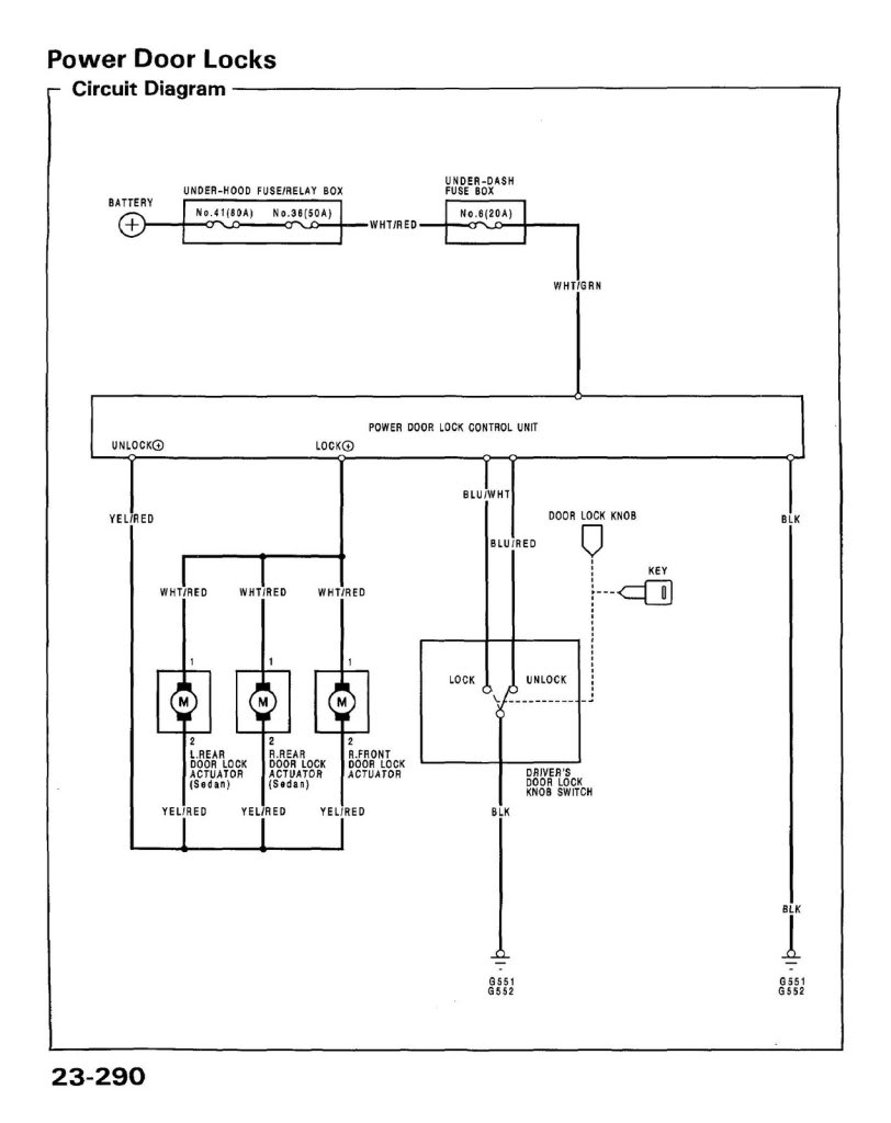
Power Door Locks & Wiring DiagramAmazon Printed Bookshttps://www.createspace.com/3623931Amazon Kindle Editionhttp://www.amazon.com/Automotive-Electronic-Diag...

Gis Kuala Kapuas Cara Pasang Alarm Dan Central Door Locks Mobil 2006 2012
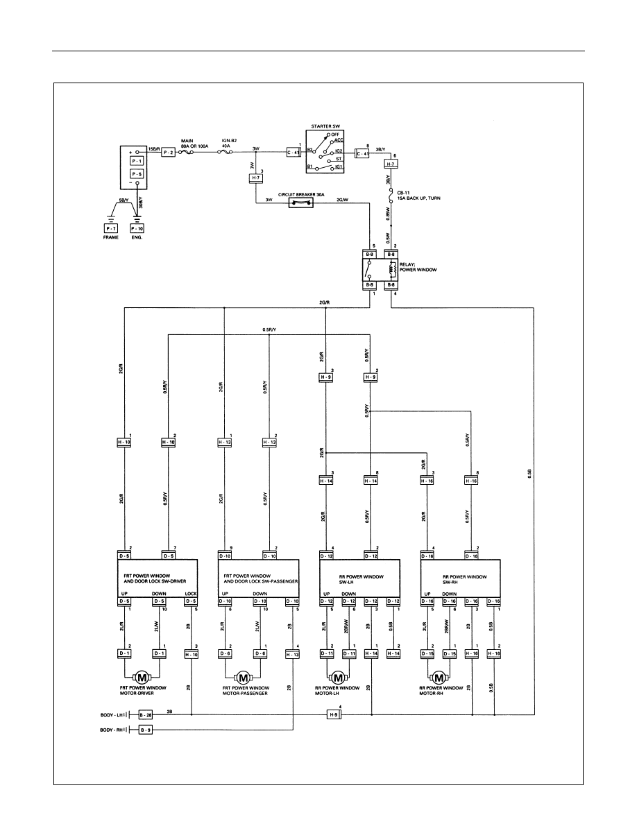
Wiring Diagrams 1. Understanding Diagrams Page U-1 Lighting Systems 1. Headlights Page L-1 2. Turnsignals & Hazard Page L-2 3. Stop Lights Page L-3 4. Automatic Light Turn-off Page L-4 5. Daytime Running Lights Page L-5 Accessories Systems 1. Rear Window Defogger Page A-1 2. Power Windows Page A-2 3. Power Mirrors Page A-3 4. Door Locks Page A ...

Gt 121 Installation Guide
12v Central Lock Universal Remote For Keyless Entry P N 900 550 Manualzz. Wiring up a keyless remote on 60 central locking for honda civic type r door lock system kit entry install car alarm with installing how vehicle electronics gps alarms systems auto 4 power bimmerforums the ultimate bmw forum do i universal e34 website vw transporter t5 12v ing installation guide actuator 5 wire relay ...

Door Locks Actuators Reverse Polarity Negative Switch Trigger Type D A Relay Wiring Diagram Door Lock System Car Audio Installation Relay
powering a lock, the minimum inductive load (lock) power wire guage shall be determined using the sdc wire guage chart or another voltage drop estimation tool. all wiring (single or multi- conductor) shall be color coded without splices. a minimum of two spare conductors is recommended. 6. voltage may not be specified on these wire diagrams. verify
Diy 92 95 Eh Eg Ej Jdm Edm Lhd Power Door Locks Honda Tech Honda Forum Discussion
power door locks wikipedia. how to wire up a 5 wire door lock actuator relay from start to finish very easy how to wire up relays and install locks on vehicles that don t come with power door locks or does not offer any analog inputs to tap you outputs from you alarm remote start on to door 5 wire 5 wire actuator wiring diagram for wiring diagram database 5 wire actuator wiring diagram for 5 ...
Buy New Universal Power Door Lock Actuator Motor Keyless 5 Wire 12 Volt 9 8lb Torque Online In Usa 222710969641
Fuel filler door is broken. Cannot open this small door. It looks like the motor for remote open door not working. I do not know if some wire is broken or motor, or microswitch which are for pushing and then the motor opens this door. The electrical wiring diagram will be very helpful for me. Will check this motor and the microswitch if are okay.
Central Door Locking Actuator 5 Wire Proteam
Diagram-5-Wire-Door-Lock-Actuator-Wiring-And-Wellreadmerhwellreadme - 5 Wire Motor Wiring Diagram. The diagram offers visual representation of a electric structure. On the other hand, this diagram is a simplified variant of the arrangement. It makes the process of building circuit easier.

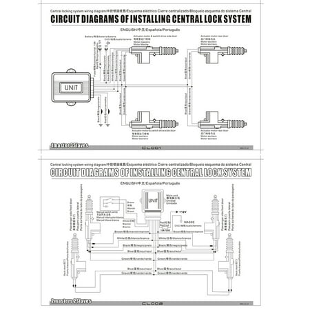
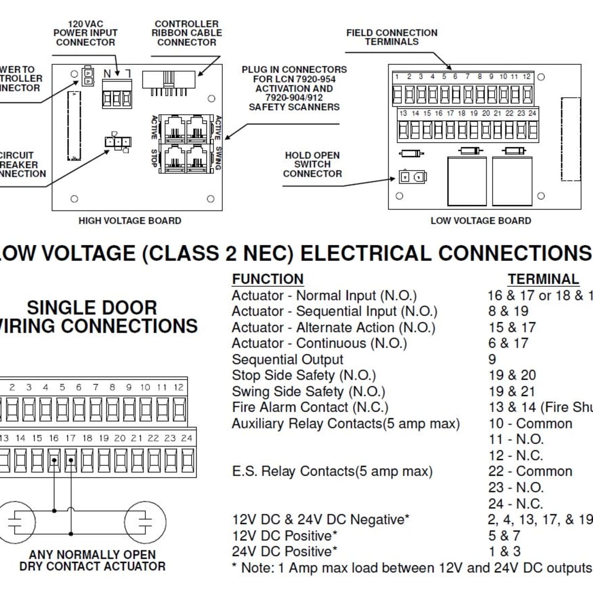
Installation Diagrams
Central Locking 5 Wire Door Lock Actuator Wiring Diagram from static-cdn.imageservice.cloud. To properly read a wiring diagram, one provides to learn how the particular components within the program operate. For instance , in case a module will be powered up and it also sends out the signal of fifty percent the voltage and the technician would ...
2
Title: CHRYSLER 3-5 WIRE DOOR LOCKS AL Author: Administrator Created Date: 8/11/2004 11:13:17 AM
All Wiring Diagrams For Mazda 5 Touring 2009 Wiring Diagrams For Cars
5-Wire Door Locks. 5-wire door locks are a bit more complicated. While the switch is off, both wires (lock and unlock) are grounded. When the switch is pushed for example to the unlock position, the unlock wire gets disconnected from the ground, and connected to +12v, activating the actuator.

Installation Diagrams
nately on lock and unlock, make sure that it is not a Type C direct-wire system. Here is a test: Cut the wire that pulses (+)12 volt on lock, and then operate the switch to unlock. If all doors unlock, the vehicle uses type A system. If you lose all door lock operation in both directions, you are operating the mas-ter switch in a Type C system.

25 5 Wire Door Lock Actuator Wiring Diagram Labels Ideas For You
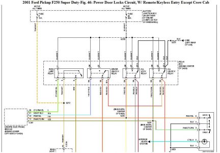
When the switch is closed, the green/white wire sends a signal to terminal 6 of the PSE, either from Green/red, or ground (brown). The PSE either sends vacuum or pressure to the door lock actuator. The green/red gets power from F4f11, so fuse 11 in the rear fuse box. Other wires at the switch are only for lighting.
How To Wire Up A 5 Wire Relay For Positive Door Locks Actuators Invert Converter Youtube
These GM wiring diagrams provide schematics for vehicle model years 1988 through 1998. Access our free Wiring Diagrams Repair Guide for GM Full-Size Trucks 1988-1998 through AutoZone Rewards. These diagrams include: Fig. 1: Index of Wiring Diagrams. Fig. 2: Sample Diagram: How to Read and Interpret Wiring Diagrams. Fig. 3: Wiring Diagram Symbols.

Modulus M11nri Instrukciya Po Ustanovke
From the thousands of photographs on the net about door lock actuator wiring diagram, we all choices the very best collections with best resolution just for you all, and this photographs is actually considered one of photos collections in this very best pictures gallery concerning Door Lock Actuator Wiring Diagram.I hope you will as it. This kind of impression (Aftermarket Door Lock Actuator ...
R49 Car Alarm Receiver User Manual Rf 215 Install Advance Security
Power Locks I Have Purchased A Power Door Lock Kit And Would Like

X Autohaux Universal Car Remote Central Kit Door Lock Vehicle Keyless Entry System Dc 12v Amazon Sg Automotive

A Safe Cs 2420

17 Universal Motorcycle Speedometer Wiring Diagram Motorcycle Diagram Wiringg Net In 2021 Types Of Electrical Wiring Diagram Autometer Gauges
Mazda Cx 5 Service Repair Manual Liftgate Opener System Doors Lids Hood Trunk
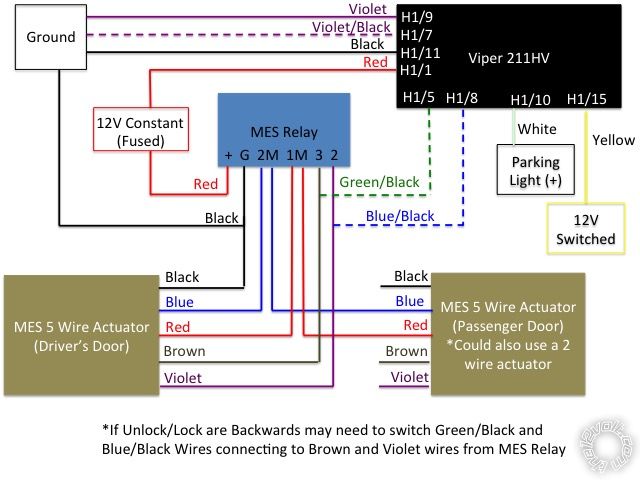
Mes Central Locking W Viper 211hv Keyless Entry
Door Locks 4 Wire Reversal Relay Wiring Diagram

Car Locking System 5 Wire Single Gun Type Central Door Lock Actuator Auto Motor Buy At The Price Of 3 36 In Aliexpress Com Imall Com
Universal Heavy Duty Power Door Lock Actuator Motor 5 Wire 12v Car Locking System Actuator Single Gun Type Kit Walmart Canada
How To Coordinate Automatic Doors With Locking Devices Dengarden

Anyone Know How The Power Door Lock Actuators Work Pelican Parts Forums
Door Locks 5 Wire Alternating 12 Volts Positive Type C Relay Wiring Diagram
Isuzu D Max Isuzu Rodeo Tfr Tfs Manual Part 1404
Features Item Type Alarm Systems Security Weight 150g Type 5 Wire Place Of Origin Guangdong China Mainland Material Plastic Metal Description Car Locking System 5 Wire 5 Wire Single Gun Type Central Door Lock Actuator 5 Wire 5 Wire Car
Acdcshop Gr

Enforcer 600 600 4 Tech Manual
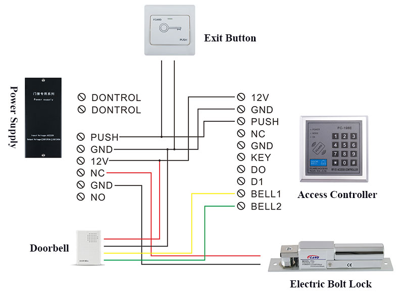
Electric Bolt Lock Fcard Premium Electric Lock Series Fcard

Relay Wire Diagram 5ab7826eea718 In 12 Volt Relay Wiring Diagram Electrical Circuit Diagram Circuit Diagram Electrical Wiring Diagram
I10 Wiring Diagrams For Remote Controlled Door Lock Hyundai Forums

Help With Understanding Power Door Lock Diagram Honda Tech Honda Forum Discussion
Multiple Wire Power Door Lock Systems Add Auto Lock Unlock

Bulldog Security Diagrams

5 Wire Door Lock Actuator Wiring Diagram Wire Center Best Of Power Door Locks Electrical Wiring Diagram Car Door Lock
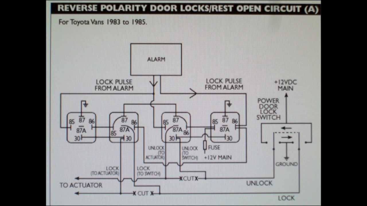
How To Wire 5 Wire Reversing Polarity Door Locks In Early Toyota And Ford Youtube
Power Door Lock Wiring Diagram Both Sides Quit At The Same Time

5 Wires Electric Lock Magnetic Output With Timer Dc12v Fail Safe Power Off To Open Door Security For Access Control System Output Aliexpress
A1 Electric Online Store Mes Door Lock Actuator 5 Wire
Security And Remote Start Installation Guide For Models Ca 6150 Ca Pdf Free Download

Universal Car Door Lock System Strong Output 2 Wires And 5 Wires Actuators 360 Degree Rotation Circle Head Waterproof Design Lock Wire Lock The Doorlock Double Doors Aliexpress
Set Kit Remot Kunci Otomatis Mobil Sistem Alarm Pengunci Pintu Sistem Penguncian Kendaraan Tanpa Kunci Dengan Pengendali Jarak Jauh M616 8217 Buy Central Mengunci Entri Tanpa Kunci Remote Mobil Keamanan Alarm 4
0 Response to "45 5 wire door lock diagram"
Post a Comment