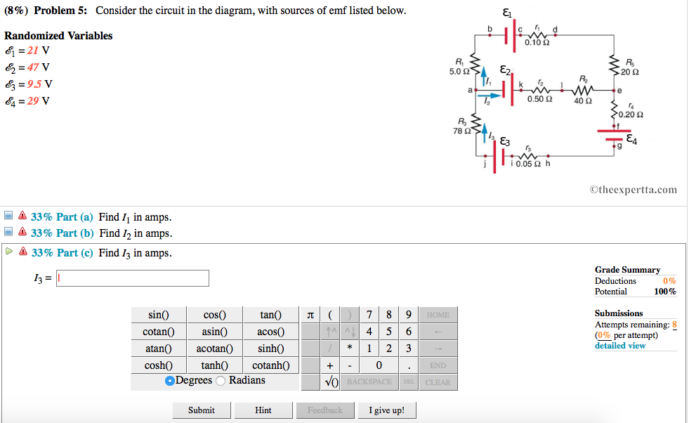
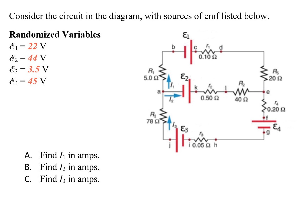
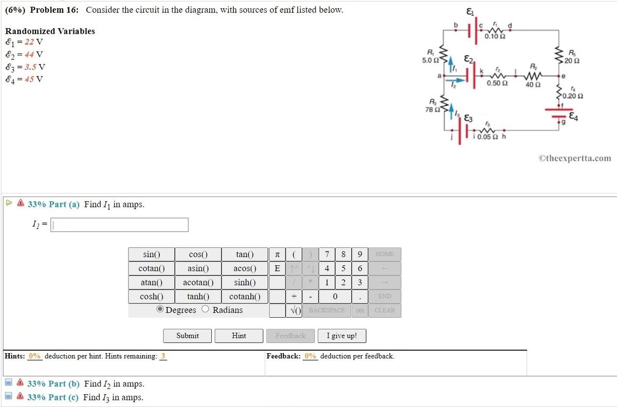
45 consider the circuit in the diagram with sources of emf listed below
Consider the circuit shown in Figure P28.9. Find ... In (c), the source of emf is traversed in the direction of the emf (from - to +), and the ... Draw the circuit diagram and assign labels and symbols to all known and unknown quantities. Assign directions to the currents. Consider the battery in the figure. The voltage of the battery is defined as the difference in electric potential between its positive and negative terminals: i.e., the points and , respectively.As we move from to , the electric potential increases by volts as we cross the emf, but then decreases by volts as we cross the internal resistor. The voltage drop across the resistor follows from Ohm ...
Links to used sources; Review your writer’s samples; Charts and PowerPoint slides; Our features. We've got everything to become your favourite writing service. Money back guarantee. Your money is safe. If we fail to satisfy your expectations, you can always request a refund and get your money back. Confidentiality . We don’t share your private information with anyone. What happens on our ...
Consider the circuit in the diagram with sources of emf listed below
This photo about: Consider the Circuit In the Diagram with sources Of Emf Listed Below, entitled as Physics Archive March 08 2018 Consider The Circuit In The Diagram With Sources Of Emf Listed Below - also describes Physics Archive March 08 2018 and labeled as: ], with resolution 1637px x 1321px The circuit diagram below shows two emf sources and a bulb connected in parallel. Also connected in the circuit is a resistor with resistance R = 0.2 . The resistance of the bulb is Rb = 0.5 , and each of the sources has internal resistance: r1 = 0.025? and r2 = 0.02 ? . The initial velocity of the ball is 20 m/s Ð 408 ABOVE HORIZONTAL. How far above or below its original level will the ball strike the opposite wall? Fig. 2-8 We have vix 20 m=s cos 408 15:3 m=s viy 20 m=s sin 408 12:9 m=s Consider ®rst the horizontal motion.
Consider the circuit in the diagram with sources of emf listed below. This photo about: Consider the Circuit In the Diagram with sources Of Emf Listed Below, entitled as Physics Archive November 10 2016 Consider The Circuit In The Diagram With Sources Of Emf Listed Below - also describes Physics Archive November 10 2016 and labeled as: ], with resolution 2025px x 1268px Electrical Troubleshooting and Electrical Repairs: Simple and Easy to Understand, including Wiring Diagrams, Step by Step Instructions and Electrical Pictures. Answer to: Consider the circuit in the diagram, with sources of emf listed below. Randomized variables: \Epsilon_1 = 22 V, \Epsilon_2 = 49V,... Walker, Jearl Fundamentals of physics / Jearl Walker, David Halliday, Robert Resnick—10th edition. volumes cm Includes index. ISBN 978-1-118-23072-5 (Extended edition) Binder-ready version ISBN 978-1-118-23061-9 (Extended edition) 1.
Electrical and Electronic Principles and Technology 3rd ed by John Bird.pdf Consider the circuit in the diagram with sources of emf listed below. The resistance of the bulb is rb 05 ohms and each of the sources has internal resistance. The circuit diagram below shows two emf sources and a bulb connected in parallel. Randomized variables varepsilon1 29 v varepsilon2 41 v. D 33 part c find 3 in amps. Consider the circuit in the diagram, with sources of emf listed below. Randomized Variables E = 22 V Ez = 44 V E3 = 3.5 V 0.10 2 R 5.0 Ω E2 202 E4 = 45 V R a 0.50 2 40 2 0.20 요 R 78 2 E3 i 0.05 2 h A. Find Ij in amps. B. Find I2 in amps. C. Find I3 in amps. Consider the circuit shown below. The terminal voltage of the battery is (a) Find the equivalent resistance of the circuit. (b) Find the current through each resistor. (c) Find the potential drop across each resistor. (d) Find the power dissipated by each resistor. (e) Find the power supplied by the battery.
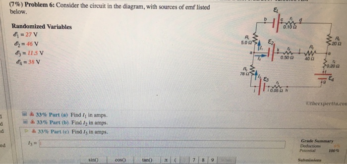
Answer to: Consider the circuit in the diagram with in the diagram with sources of emf listed below Randomized variable E 1 = 25 v E 2 = 46v ... The label on a battery-powered radio recommends the use of a rechargeable nickel-cadmium cell (nicads), although it has a 1.25-V emf, whereas an alkaline cell has a 1.58-V emf. The radio has a 3.20 Ω 3.20 Ω resistance. (a) Draw a circuit diagram of the radio and its battery. 17.02.2019 · The diagram below shows a potentiometer set up. On touching the jockey near to the end X of the potentiometer wire, the galvanometer pointer deflects to left. On touching the jockey near to end Y of the potentiometer, the galvanometer pointer again deflects to left but now by a larger amount. Identify the fault in the circuit and explain, using appropriate equations or otherwise, how it leads ... Question: (9%) Problem 6: Consider the circuit in the diagram, with sources of emf listed below Randomized Variables 81-29 V 0.1 R, 20Ω 83-6.5 V 84-43 V 0.50 Ω 40Ω 020 Ω 78 Ctheexpertta.c Li 33% Part (a) Find 11 in amps. 33% Part (b) Find 12 in amps. 33% Part (c) Find 13 in amps.
Academia.edu is a platform for academics to share research papers.

Energies Free Full Text Analysis And Design Of A Multi Port Dc Dc Converter For Interfacing Pv Systems Html
Consider the circuit shown in the diagram below where. Consider the circuit in the diagram with sources of emf listed below. The sum of all potential changes around a closed loop is zero junction rule. Homework statement consider the circuit shown in the diagram below for r1 5 ω r2 8 ω r3 8 ω r4 8 ω and v0 80 v. Find i2 in amps. Find i3 in ...

Noncontrolled Fault Current Limiter With Reactive Power Support For Transient Stability Improvement Of Dfig Based Variable Speed Wind Generator During Grid Faults Fdaili 2021 International Transactions On Electrical Energy Systems
All the papers we deliver to clients are based on credible sources and are quality-approved by our editors. Fast Turnaround Our writers can complete a standard essay for you within 1-3 hours and a part of a dissertation – in 2-5 days.
Consider the Circuit In the Diagram with sources Of Emf Listed Below. training ueeneee104a solve problems in d c australian government department of education and training training gov au magnetic shielding materials emf safety superstore circuit breaker shield decorative magnetic shielding a circuit breaker box or fuse box in the bedroom living room kitchen or other living space can
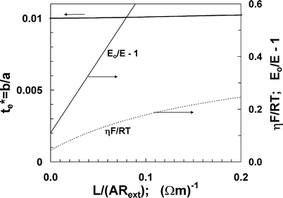
Applicability Of Emf Measurements Under External Load Resistance Conditions For Ion Transport Number Determination Springerlink
Consider the circuit in 1 the diagram with sources of emf listed below. With resolution 1637px x 1321px. The circuit diagram below shows two emf sources and a bulb connected in parallel. Randomized variables ac 1 29 v ac 2 41 v ac 3 45 v ac 4 35 v. Consider the two loads in the circuit below load brushless dc bldc motor with arduino part 2 ...

Wireless Power Transfer And Telemetry For Implantable Bioelectronics Yoo 2021 Advanced Healthcare Materials Wiley Online Library
Problem 6: Consider the circuit in the diagram, with sources of emf listed below Randomized Variables EI-25 V & 49 V 0.102 5.0 Ω 20Ω R2 0.50 Ω 40Ω 4 31 V 0.20 Ω Ra 9 ¡0.05 Ω h Otheexpertta.com Part (a) Find /1 in amps. . tan( cos(0) cotan0asin) acos(0 sin() 4 5 6 *1 23 0 atan()acotan( sinh() cosh)tanh) cotanh O Degrees O Radians BACKSPACE CLEA Submit Hint I give up!

This Is The Third Time Ive Posted This Question And Have Received Wrong Answers For All Parts Homeworklib
Problem 4: Consider the circuit in the diagram, with sources of emf listed below. Randomized Variables ℰ 1 = 25 V ℰ 2 = 44 V ℰ 3 = 14 V ℰ 4 = 28 V. Part (a) Find I 1 in amps. Numeric: A numeric value is expected and not an expression. I 1 = _____ Part (b) Find I 2 in amps. Numeric: A numeric value is expected and not an expression.

Consider The Circuit In The Diagram With Sources Of Emf Listed Below Randomized Variables Epsilon 1 22 V Epsilon 2 49v Epsilon 3 7 5v Epsilon 4 45 V A Find I 1 In Amps B
(b) The circuit diagram of the two batteries and the load resistor, with each battery modeled as an idealized emf source and an internal resistance. When voltage sources are in series, their internal resistances can be added together and their emfs can be added together to get the total values.

State Of Charge Estimators Considering Temperature Effect Hysteresis Potential And Thermal Evolution For Lifepo4 Batteries Xie 2018 International Journal Of Energy Research Wiley Online Library
2. The source that maintains the constant currentin a closed circuit is called a source of "emf." a) One can think of such a source as a "charge pump" =⇒ forces electronstomove in adirection oppositetheE-field, hence current, inside a source. b) The emf, E, of a source is the work done per unit charge =⇒ measured in volts. c) A ...
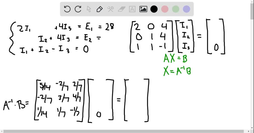
Solved 109 Problem 7 Consider The Circuit In The Diagram With Sources Of Emf Listed Below Randomized Variables 8j 23v 62 46 V 6 105v 64 46v Od 20 40 4
My question is, is the snubber in your circuit below (I’ve just re-drawn it so I’ve got the pin outs on it) sufficient for this circuit as on another of your pages you recomend using a 100 ohm 50 watt resistor with a 330nF 1kv capacitor for general use. I’ve also noted that on your twin coil circuit that there’s no snubber. Am I right in thinking thats because they counteract each ...
Basic Electrical Installation Work, Fourth Edition
The in the with of emf listed randomized variables 6 29 v 502 47 85 45 78 q a. Consider the circuit in the diagram with sources of emf listed below. I know the top one is stronger so the current is traveling in a counter clockwise manner but dont know the technique when there are two emf sources for solving the magnitude of the current.
Cheap essay writing sercice. If you need professional help with completing any kind of homework, Solution Essays is the right place to get it. Whether you are looking for essay, coursework, research, or term paper help, or with any other assignments, it is no problem for us.
Solution for (6%) Problem 16: Consider the circuit in the diagram, with sources of emf listed below. Randomized Variables 0.10 2 E1 = 22 V E2 = 44 V Ez = 3.5 V…
Questions 14-15 refer to the following diagram that shows part of a closed electrical circuit. 14. The electrical resistance of the part of the circuit shown between point X and point Y is (A) 4/3 (B ) 2 (C) 4 (D) 6 15. When there is a steady current in the circuit, the amount of charge passing a point per unit of time is
a. In a space below draw a diagram showing all the elements connected In one electrical circuit that can provide the maximum rate of heat produced. Use two meters in your circuit. they will help to measure the heat rate The battery has an emf of 12 V and an internal resistance of 0.5 Q and each heating coil has a resistance of 17.3 Q
This photo about: Consider the Circuit In the Diagram with sources Of Emf Listed Below, entitled as Electrical Engineering Archive November 01 2014 Consider The Circuit In The Diagram With Sources Of Emf Listed Below - also describes Electrical Engineering Archive November 01 2014 and labeled as: ], with resolution 1958px x 1457px
It is very easy. Click on the order now tab. You will be directed to another page. Here there is a form to fill. Filling the forms involves giving instructions to your assignment. The information needed include: topic, subject area, number of pages, spacing, urgency, academic level, number of sources, style, and preferred language style.
(7%) Problem 3: Consider the circuit in the diagram, with sources of emf listed below, ca 0.10 0 Randomized Variables E = 22 V 5.0 20 0 EL = 42 V [T, KyHe 1 0.50 40 a . E3 = 6.5 V a E4 = 38 v 0.20 0 78 a ji 05 a h Otheexpertta.com A 33% Part (a) Find I1 in amps. a 33% Part (b) Find 12 in amps.
Problem: Consider the circuit in the diagram, with sources of emf listed below.Randomized Variablesℰ1 = 21 Vℰ2 = 49 Vℰ3 = 9.5 Vℰ4 = 39 Va) Find I1 in amps.B) Find I2 in amps.C) Find I3 in amps.

Frontiers Lipid Body Dynamics In Shoot Meristems Production Enlargement And Putative Organellar Interactions And Plasmodesmal Targeting Plant Science
Consider the circuit in the diagram with sources of emf listed below. Homework Questions From 10 Print Outs Phy 317l General Physics View the full answer. Consider the circuit in the diagram with sources of emf listed below. C a battery is a good example of a source of emf. 2616 consider the circuit sketched.

Consider The Circuit In The Diagram With Sources Of Emf Listed Below E1 27v E2 41v E3 7 5v Homeworklib
Consider the circuit below. ... Calculate the current flowing through the source of emf in this circuit. Unit 1 Physics 2017 Electricity Page 5 of 25. Questions 39 to 41 refer to the following circuit diagram. Question 39 . Find the effective resistance of this circuit.
The initial velocity of the ball is 20 m/s Ð 408 ABOVE HORIZONTAL. How far above or below its original level will the ball strike the opposite wall? Fig. 2-8 We have vix 20 m=s cos 408 15:3 m=s viy 20 m=s sin 408 12:9 m=s Consider ®rst the horizontal motion.
The circuit diagram below shows two emf sources and a bulb connected in parallel. Also connected in the circuit is a resistor with resistance R = 0.2 . The resistance of the bulb is Rb = 0.5 , and each of the sources has internal resistance: r1 = 0.025? and r2 = 0.02 ? .
This photo about: Consider the Circuit In the Diagram with sources Of Emf Listed Below, entitled as Physics Archive March 08 2018 Consider The Circuit In The Diagram With Sources Of Emf Listed Below - also describes Physics Archive March 08 2018 and labeled as: ], with resolution 1637px x 1321px
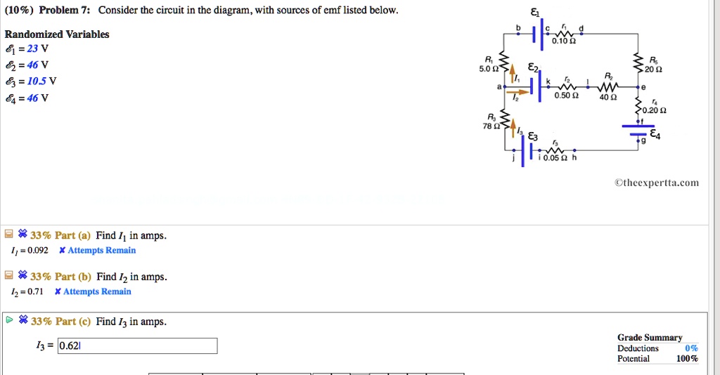
Solved 109 Problem 7 Consider The Circuit In The Diagram With Sources Of Emf Listed Below Randomized Variables 8j 23v 62 46 V 6 105v 64 46v Od 20 40 4
Air Pollution Measurement Techniques Report And Proceedings Of The Wmo Air Pollution Measurement Techniques Conference Apomet

Electronics Free Full Text Electromagnetic Field Based Wpt Technologies For Uavs A Comprehensive Survey Html

10 Problem 10 Consider The Circuit In The Diagram With Sources Of Emf Listed Below 5 023 E2 Randomized Variables 28 V E2 43 V Ez 11 V E 41 V 02 Me 400 78 22 Tea W 10 050 H

Theoretical And Experimental Investigations On Optimization Of The Received Power Of A Monopole Antenna Iopscience

Consider The Circuit In The Diagram With Sources Of Emf Listed Below Randomized Variables Varepsilon 1 29 V Varepsilon 2 41 V Varepsilon 3 4 5 V Varepsilon 4 35 V Study Com

10 Problem 10 Consider The Circuit In The Diagram With Sources Of Emf Listed Below 5 023 E2 Randomized Variables 28 V E2 43 V Ez 11 V E 41 V 02 Me 400 78 22 Tea W 10 050 H

Consider The Circuit In The Diagram With Sources Of Emf Listed Below Randomized Variables Varepsilon 1 29 V Varepsilon 2 41 V Varepsilon 3 4 5 V Varepsilon 4 35 V Study Com

A Novel Space Vector Modulation Based Transistor Clamped H Bridge Inverter Fed Permanent Magnet Synchronous Motor Drive For Electric Vehicle Applications Jayal 2021 International Transactions On Electrical Energy Systems Wiley Online Library







0 Response to "45 consider the circuit in the diagram with sources of emf listed below"
Post a Comment