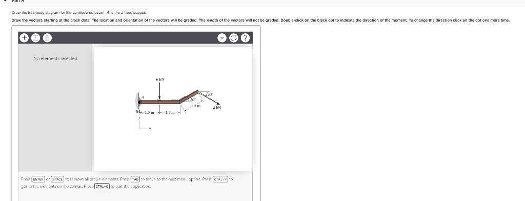
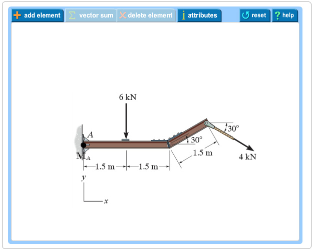
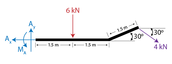
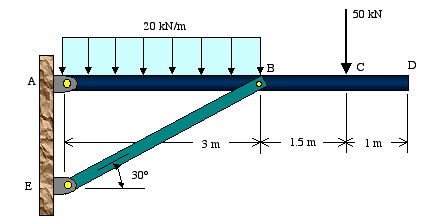
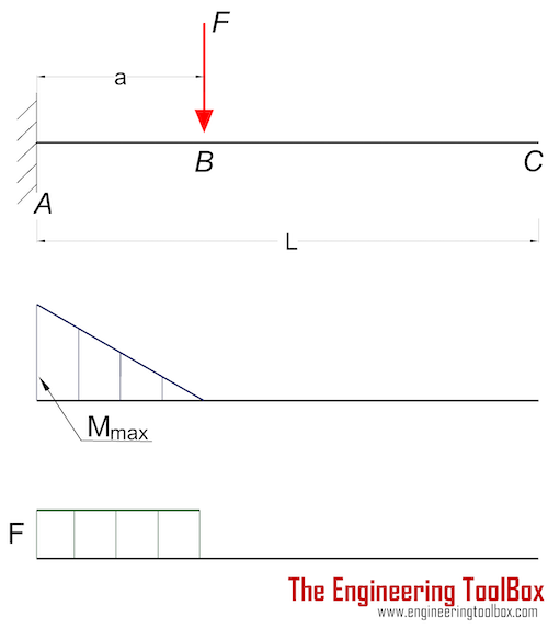
40 draw the free-body diagram for the cantilevered beam. a is the a fixed support.
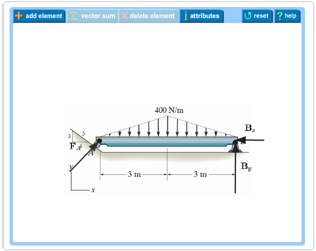
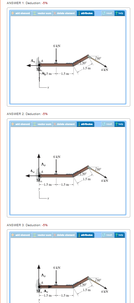
Mechanical Engineering questions and answers. Draw the free-body diagram for the cantilevered beam. A is the a fixed support. Draw the vectors starting at the black dots. The location and orientation of the vectors will be graded. The length of the vectors will not be graded. Double-click on the back dot to indicate the direction of the moment.
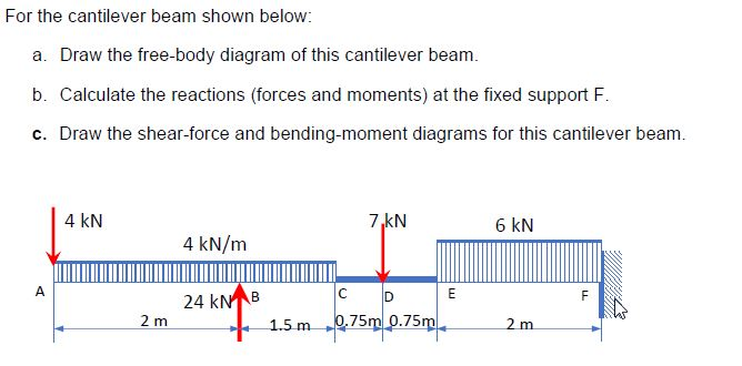
As a general rule, if a support prevents translation of a body in a given direction, ... Draw the free body diagram: R ... A cantilever beam is loaded as shown. Determine all reactions at support A. 5 kN/m 2 m 2 m 1 m A 20 kN 3 4 15 kNm EXAMPLE 3 .
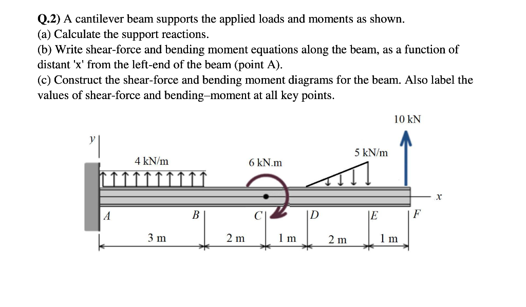
Figure 4.1 Statically determinate beams A cantilever beam is built into a rigid support at one end, with the other end being free, as shown in Fig.4.1(b). The built-in support prevents displacements as well as rotations of the end of the beam.

Draw the free-body diagram for the cantilevered beam. a is the a fixed support.
https://goo.gl/P5AUbb for more FREE video tutorials covering Engineering Mechanics (Statics & Dynamics)The key objective of this video is to consider support...
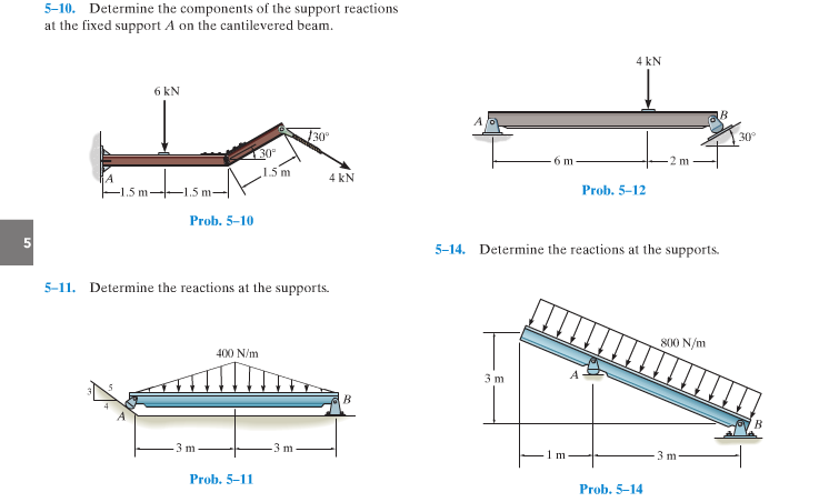
Draw the vectors starting at the black dots. Our first step is to draw a free body diagram like so. Determine the components of the support reactions at the fixed support a on the cantilevered beam. A y 4knd 0 m a. The cantilever is a beam which has one end free and the other is fixed.
Determine the components of the support reactions at the fixed support a on the cantilevered beam
Draw the free-body diagram for the cantilevered beam. a is the a fixed support..
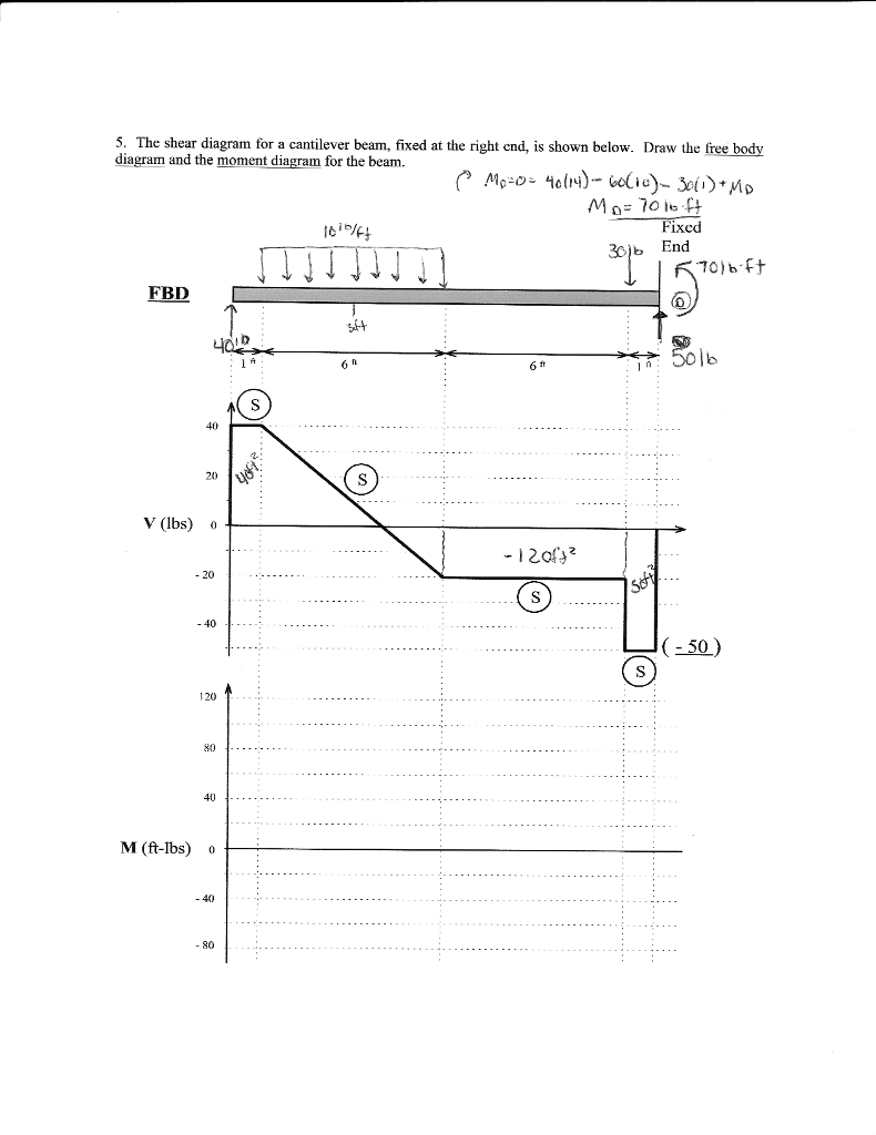
Draw the free body diagram for the cantilevered beam. If a beam is cantilevered it has a fixed support at one end which is the right end for this beam the beam weighs 150 lbft and the weight of the beam acts through its centroid. The wall holds the cantilever beam. All the reaction components will be experienced only on the fixed end.
beam. The bending moment acting at the distance x from the left end can be obtained from the free-body diagram in Fig. (b) (note that V and M are shown acting in their positive directions): 2 2 2 0 0 x w x M =−w x =− Substituting the expression for M into the differential equation EIυ”= M, 2 2 EIυ" =− w 0 x
Free online beam calculator for generating the reactions, calculating the deflection of a steel or wood beam, drawing the shear and moment diagrams for the beam. This is the free version of our full SkyCiv Beam Software. This can be accessed under any of our Paid Accounts, which also includes a full structural analysis software.
Draw the free-body diagram for the cantilevered beam. A is the a fixed support Draw the vectors starting at the black dots. The location and orientation of the vectors will be graded. The length of the vectors will not be graded. Double-click on the black dot to indicate the direction of the moment.
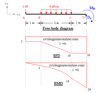
Drawing a correct free-body diagram is the first and most important step in the process of solving an equilibrium problem. It is the basis for all the equilibrium equations you will write; if your free-body diagram is incorrect then your equations, analysis, and solutions will be wrong as well. ... Fixed support. The cantilevered beam is ...
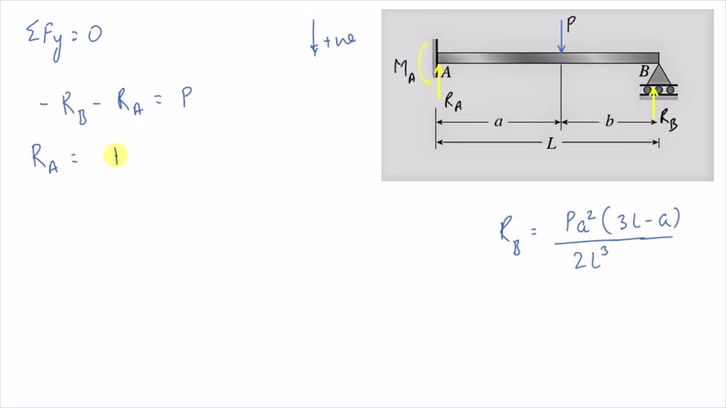
A propped cantilever beam a b of length l carries a concentrated load p acting at the position shown















0 Response to "40 draw the free-body diagram for the cantilevered beam. a is the a fixed support."
Post a Comment