44 converging lens ray diagram
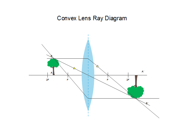
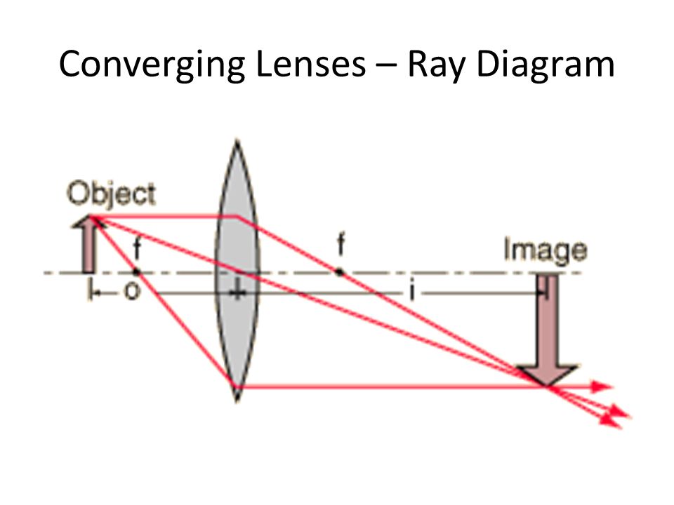
Ray diagram for converging lens. Ray 1 is parallel to the axis and refracts as if from F. Ray 2 heads towards F’ before refracting parallel to the axis. Ray 3 passes straight through the center of the lens. image is always virtual, upright and reduced O F I F’ Ray diagram for diverging lens
11.10.2021 · Which diagram shows image formation of an object on a screen by a converging lens?Answer -While drawingray diagram, we follow these rulesA rayparallel tothe principalaxiswill pass through the principal focus.A raypassing throughthe principalfocuswill become parallel to the principal axis.A raypassin
This Demonstration lets you visualize the ray diagrams for converging and diverging lenses. By manipulating the object and lens locations, you can create real or virtual images. The rays parallel to the principal axis and the ray through the center of the lens are drawn.Locators allow you to drag both the object and the lens. You can change the focal length using a slider.

Converging lens ray diagram
Concave lens; Convex lens; A ray diagram of a concave lens and the convex lens is shown below; Concave Lens. A concave lens is a type of lens with at least one side curved inwards. A concave lens with both sides curved inward is known as a biconcave lens. Concave lenses are diverging lenses, that is, they spread out light rays that have been refracted through it. They …
Ray Diagrams By constructing a ray diagram, we can determine where the image is located, and what it will look like. A ray diagram is a diagram showing rays that can be drawn to determine the size and location of an image formed by a mirror or lens.
03.10.2020 · 1. Concave lens is also known as 2. Mirror used as rear view mirror 3. Mirror used by dentist 6. A point on principal axis of lens where all rays of light parallel to the principal axis meets or appear to meet. 7. The image which can be obtained on screen. Answer. Answer: Across: 4. Refraction 5. One 8. Converging lens. Down: 1. Diverging lens ...
Converging lens ray diagram.
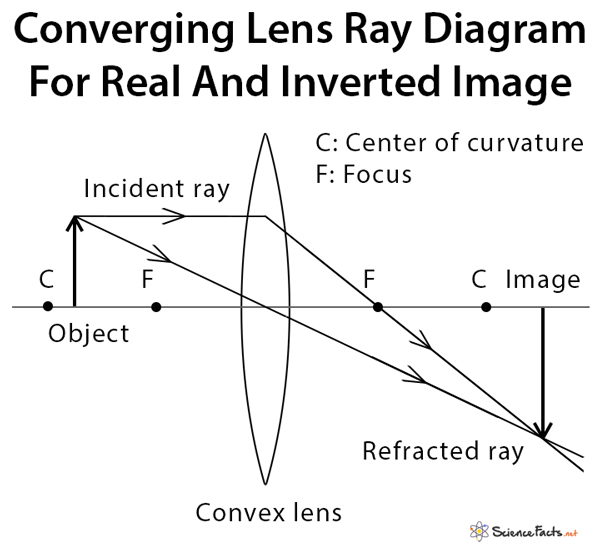
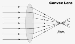
A converging lens is an optical lens that converges all rays of light passing through it. The primary purpose of a converging lens is to focus the incoming rays from an object and converge them to form an image. The image can be magnified, diminished, or remain the same depending on the distance of the object from the lens.
24.01.2019 · Item Number Stihl String Trimmer Air . stihl fs 56 parts diagram is probably the photos we found on the online from reliable sources. We choose to discuss this stihl fs 56 parts diagram photo on this page just because based on facts coming from Google search engine, It is one of the best searches keyword on google. FS 56, FS 56 R, FS 56 C, FS 56 RC English 2 …
A ray diagram using this virtual object shows the location of the final image (bottom part of Figure O). Numerically, we can verify the accuracy of the ray diagram with: An arrow is placed 50 cm away from a converging lens (f= 25cm). On the other side of this first lens is a second converging lens (f. Ray Diagrams for Lenses. The image formed ...
The ray diagram(Fig.1) formed by the combination of two convex lenses has the following attributes: u = Object-distance for the first lens. v = final image-distance for the second lens \[v_{1}\] = image-distance for the first image I1 for the first lens. As the lenses are pretended to be thin, \[v_{1}\] is also the object-distance for the second lens. The lens formula for the image …
30 Oct 2014 — SS: Ray Diagrams For Converging Lens · There is one ray of light passing through the center of the lens. · 2 rays are enough to determine the ...
Two Converging Lens Ray Diagram. Examples are given for converging and diverging lenses and for the cases where the The third ray is not really needed, since the first two locate the image. In this section of Lesson 5, we will investigate the method for drawing ray diagrams for objects placed at various locations in front of a double convex lens.
Convex (converging) and concave (diverging) lenses are drawn as, V W To understand image formation we use ray diagrams. Here is an example for aconvex lens: F The image of the top of the object is formed where the light rays cross. In a perfect lens all the rays from a point on the object will meet at one other point - so we only need to draw two rays! Section 1: Introduction …
5) virtual, inverted, and diminished. Page 7. A real image is formed by a converging lens. If a weak ...15 pages
Here you have the ray diagrams used to find the image position for a converging lens. You can also illustrate the magnification of a lens and the difference between real and virtual images. Ray diagrams are constructed by taking the path of two distinct rays from a single point on the object. A light ray that enters the lens is an incident ray.
Click here👆to get an answer to your question ️ An object is placed 50 cm from a lens produces a virtual image at a distance of 10 cm in front of the lens. Draw a diagram to show the formation of image and calculate the focal length of the lens.
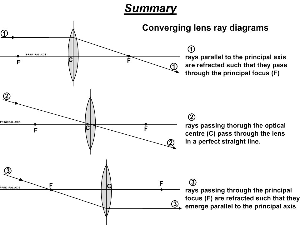
To explain how to draw the diagrams, there are two key things to remember. 1 A converging lens refracts the light so that any ray of light parallel to the principal axis (the thick horizontal line) is turned to pass through the focal point. Rays of light parallel to the principal axis are all refracted through the focal point.
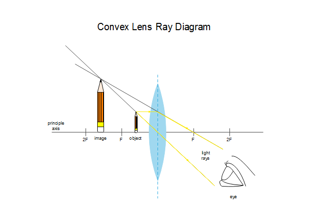
Draw a ray diagram to show how a converging lens is used as a magnifying glass to observe a small object. Mark on your diagram the foci of the lens and the position of the eye. Solution: The object is placed between the focal point F 1 and convex lens and its image is formed at the same side of the lens which is enlarged. Hence, this lens can be used as a magnifying lens. …
Ray diagrams for lenses
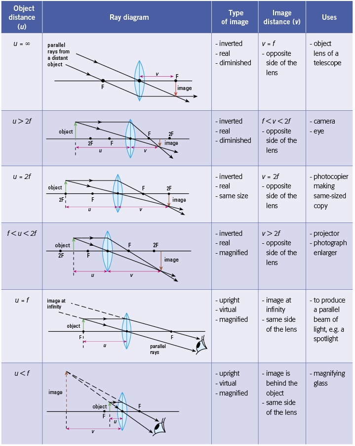
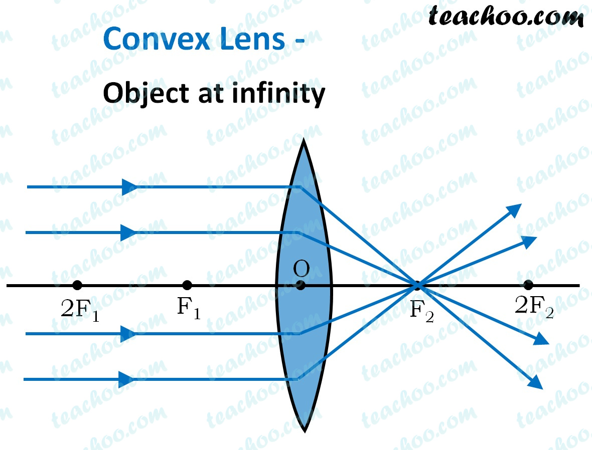
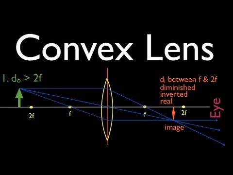
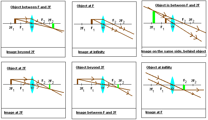
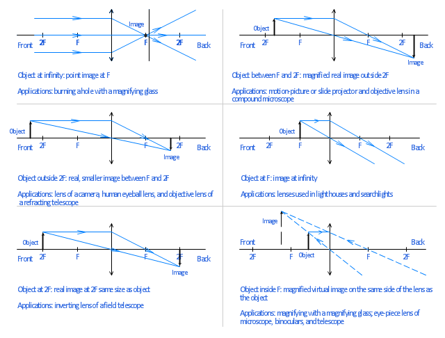
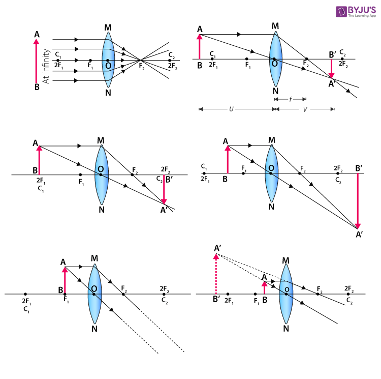
18 Nov 2021 — For a Convex Lens, object can be kept at different positionsHence, we take different casesCase 1 - Object is Placed at infinityIn this Case, ...Position of the object: Position of the imageAt 2F 1 : At 2F 2Beyond 2F 1 : Between F 2 and 2F ...At focus F 1 : At infinity
Ss: ray diagrams for converging lens - mini physics - learn ...
The Physics Classroom » Curriculum Corner » Refraction and Lenses » Ray Diagrams for Converging Lenses. The document shown below can be downloaded and printed. Teachers are granted permission to use them freely with their students and to use it as part of their curriculum. Visit the Usage Policy page for additional information.
Ray diagrams for lenses
A lens is a transmissive optical device which focuses or disperses a light beam by means of refraction.A simple lens consists of a single piece of transparent material, while a compound lens consists of several simple lenses (elements), usually arranged along a common axis.Lenses are made from materials such as glass or plastic, and are ground and polished or molded to a …
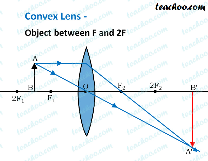
Convex lens - ray diagram, image formation, table - teachoo
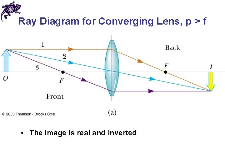
Ray Diagrams for Lenses. The image formed by a single lens can be located and sized with three principal rays. Examples are given for converging and diverging lenses and for the cases where the object is inside and outside the principal focal length. The "three principal rays" which are used for visualizing the image location and size are:
Converging lens: definition, diagram, equation & application
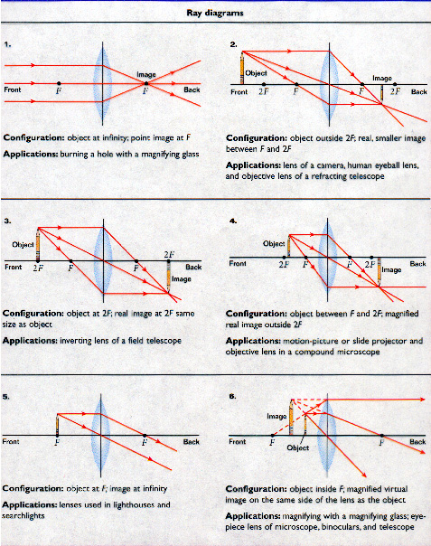
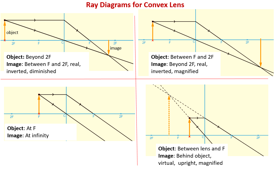
Ray Diagram for Object Located in Front of the Focal Point. In the three cases described above - the case of the object being located beyond 2F, the case of the object being located at 2F, and the case of the object being located between 2F and F - light rays are converging to a point after refracting through the lens. In such cases, a real image is formed.

Drawing ray diagrams for a converging lens - the fizzics ...
Physics tutorial: refraction and the ray model of light
Ray diagrams (2 of 4) convex lens

Pin on refraction and lenses

Image formation by convex and concave lens ray diagrams

The open door web site : ib physics : optics : ray diagrams ...

Lesson explainer: drawing ray diagrams for convex lenses | nagwa
Ray diagrams for lenses
Convex lens ray diagram | free convex lens ray diagram templates
Ray diagrams for convex lens - online science home work
Convex lens - ray diagram, image formation, table - teachoo
The photons of light then travels in all directions - simple ...

The open door web site : ib physics : optics : ray diagrams ...
Ray tracing diagram for convex lens | physics diagrams ...
Lenses - stickman physics

Nature of images by a convex and concave lenses - with ray ...

Lens ray diagram worksheet | pdf

1 principal ray diagram for a thin converging lens. in this ...

Human eye optics
Physics tutorial: refraction and the ray model of light

Lenses, ray diagrams for convex lenses

Ray diagrams for lenses royalty free vector image

Physics - optics: lenses (2 of 5) lens combinations - two converging lenses

Sketch a ray diagram for a spherical convex lens with an ...
Gcse physics - ray diagram for an image made by a convex lens ...
Images formed by lenses ray diagrams for lenses ray diagrams ...
One side convex lens ray diagram | free one side convex lens ...

Lens ray diagram worksheet | pdf

20140227 converging diverging lens ray diagram worksheet
---teachoo.png)
Convex lens - ray diagram, image formation, table - teachoo

Open source physics @ singapore: ejss thin converging ...
Chapter 31 images mirrors and lenses definitions images
Waves drawing ray diagrams for converging lenses. - ppt download

Action of a thin converging lens | definition, examples, diagrams
To find image distance for varying distance of a concave lens
Ray tracing lenses

Ray diagrams for image formation of (a) converging (bi-convex ...
Convex lenses and ray diagrams (examples, solutions, videos ...
0 Response to "44 converging lens ray diagram"
Post a Comment