45 how to read a moody diagram
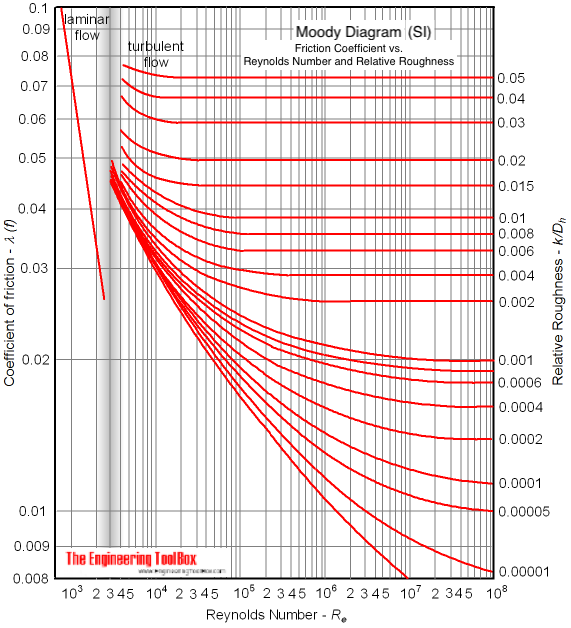
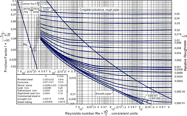
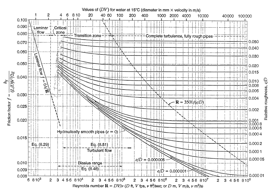
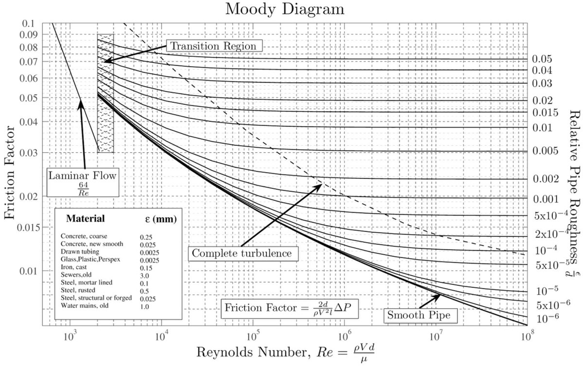
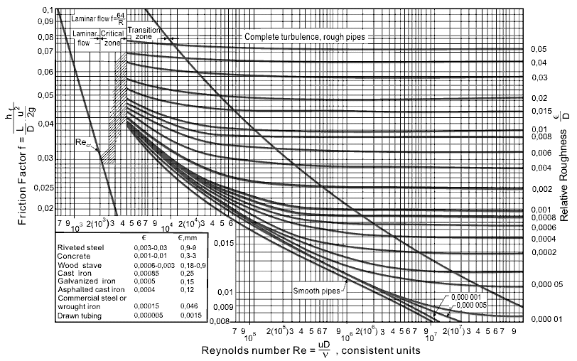
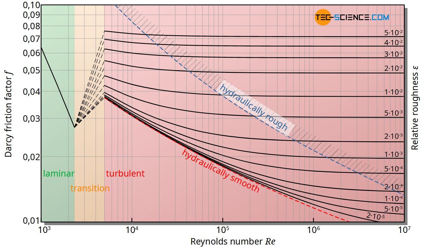
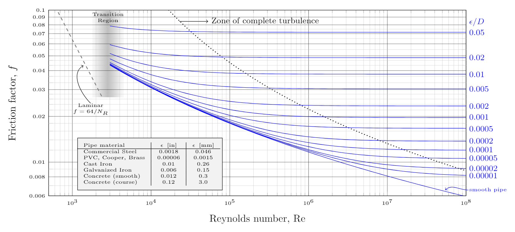
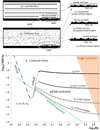
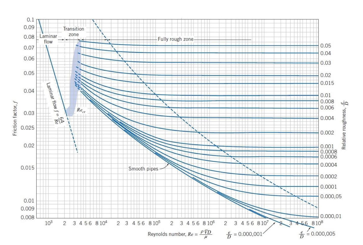
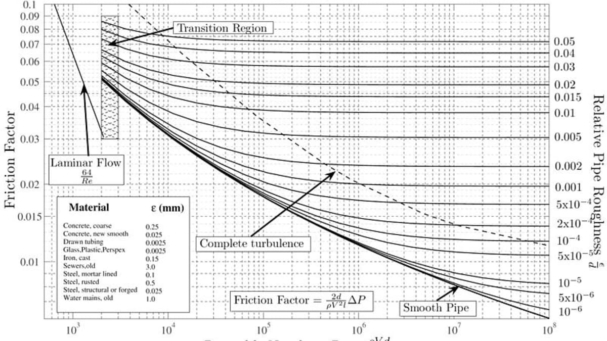
SI based Moody Diagram The Moody friction factor - λ (or f) - is used in the Darcy-Weisbach major loss equation. The coefficient can be estimated with the diagram below: If the flow is transient - 2300 < Re < 4000 - the flow varies between laminar and turbulent flow and the friction coefiicient is not possible to determine.
In this video I walk you threw reading the Moody diagram. The moody diagram is useful in obtaining the friction factor for a closed pipe system.
An introduction to the famous Moody Chart! We use the Moody Chart often to estimate frictional factors. To download the notes I use for these videos, please ...

How to read a moody diagram
MOODY DIAGRAM Friction factors for any type and size of pipe. (From Pipe Friction Manual, 3rd ed., Hydraulic Institute, New York, 1961) O O = J uopeJ UO!IOUJ uoeqs!êM-Á0Jea S C o i. (ww u! a 'wul u! 3) = J ssauuôno' Title: Microsoft Word - Moodies diagram.doc Author: Administrator
Moody's charts. 1. . A WATER RESOURCES TECHNICAL PUBLICATION ENGINEERING MONOGRAPH NO. 27 Moments and Reactionsfor Rectangular Plates UNITED STATES DEPARTMENT OF THE INTERIOR BUREAU OF RECLAMATION. 2. A WATER RESOURCES TECHNICAL PUBLICATION Engineering Monograph NO.
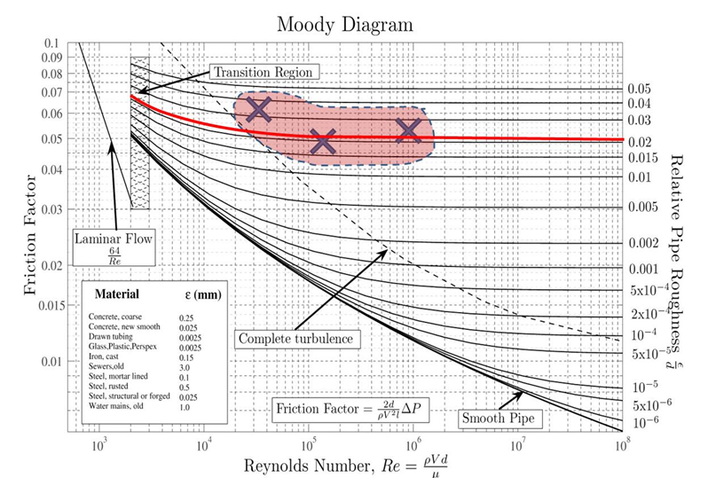
Another common mistake when reading the Moody Diagram is improper interpolation between lines and points. Be aware of the logarithmic nature of the axes and labels values, halfway between the values is NOT halfway between the points This system will only work for steady state analysis.
How to read a moody diagram.
The Moody chart (also known as the Moody diagram) is a graph in non-dimensional form that relates the Darcy friction factor, Reynolds number, and the relative roughness for fully developed flow in a circular pipe. Reynolds Number. The Reynolds number is the ratio of inertial forces to viscous forces and is a convenient parameter for predicting ...
1) the red line is in the wrong place for Reynolds number of 2.11x10 4. Check again. 2) The orange line should follow the relative roughness curve until it crosses the red line. i.e. Once you have the correct Reynolds number line position, find the relative roughness value line of 0.015 and follow it right to left as it curves upwards (left of ...
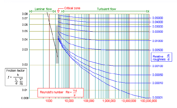
The blue lines plot the friction factor for flow in the wholly turbulent region of the chart, while the straight black line plots the friction factor for flow in the wholly laminar region of the chart. Friction Chart or Moody Chart The value of f, Darcy friction factor is taken from Moody Diagram.
This photo about: How to Read A Moody Diagram, entitled as How To Read Moody Diagram - Estimation Articular Cartilage How To Read A Moody Diagram - also describes How To Read Moody Diagram - Estimation Articular Cartilage and labeled as: ], with resolution 2092px x 3877px
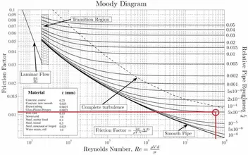
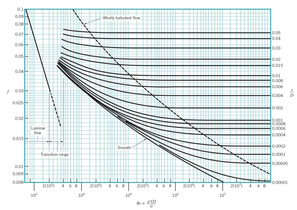
23 How To Use Moody Diagram. If the flow is transient 2300 re 4000 the flow varies between laminar and turbulent flow and the friction coefiicient is not possible to determine. Using the moody chart a reynolds number of 50 000 000 intersects the curve corresponding to a relative roughness of 5 x 10 5 at a friction factor of 0011.
Download the free Moody Chart Calculator app from Google Play here . Learn more about the Moody Chart Calculator here .
In engineering, the Moody chart or Moody diagram (also Stanton diagram) is a graph in non-dimensional form that relates the Darcy-Weisbach friction factor f D, Reynolds number Re, and surface roughness for fully developed flow in a circular pipe. It can be used to predict pressure drop or flow rate down such a pipe.
CARA MEMBACA GRAFIK MOODY (DIAGRAM MOODY) - BATANG - 2021. Saat menyelesaikan banyak masalah dinamika fluida, baik itu kondisi tunak atau transien, faktor gesekan Darcy-Weisbach, f , diperlukan. Dalam pipa lingkaran, faktor ini dapat diselesaikan secara langsung dengan persamaan Swamee-Jain, serta persamaan lainnya, namun sebagian besar ...
Explains how to read a Moody chart for determining frictional factors in pipe flow problems. Made by faculty at the University of Colorado Boulder, Departmen...
About Press Copyright Contact us Creators Advertise Developers Terms Privacy Policy & Safety How YouTube works Test new features Press Copyright Contact us Creators ...
Example: Moody Diagram. Using the Moody diagram, determine the friction factor (f D) for fluid flow in a pipe of 700mm in diameter with a Reynolds number of 50 000 000 and an absolute roughness of 0.035 mm. Solution: The relative roughness is equal to ε = 0.035 / 700 = 5 x 10⁻⁵.Using the Moody Chart, a Reynolds number of 50 000 000 intersects the curve corresponding to a relative roughness of ...
In engineering, the Moody chart or Moody diagram is a graph in non-dimensional form that relates the Darcy-Weisbach friction factor f D, Reynolds number Re, and relative roughness for fully developed flow in a circular pipe. In fluid dynamics we have to solve problems which involves the use of Darcy-Weisbach friction factor f. Whether the flow is steady or transient we have to use it.
Correction: At 2:00, the friction factor is about 0.034, not 0.032.
I also commented out some of the boxes because it was blocking out my data. function moody (units,paper,name) % Moody Diagram (R13) % MOODY (UNITS,PAPER,NAME) generates a four axis, publication quality. % Moody diagram as a PAPER size encapsulated postscript file NAME with. % UNITS.
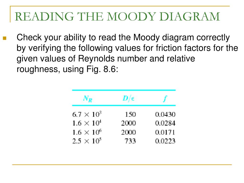
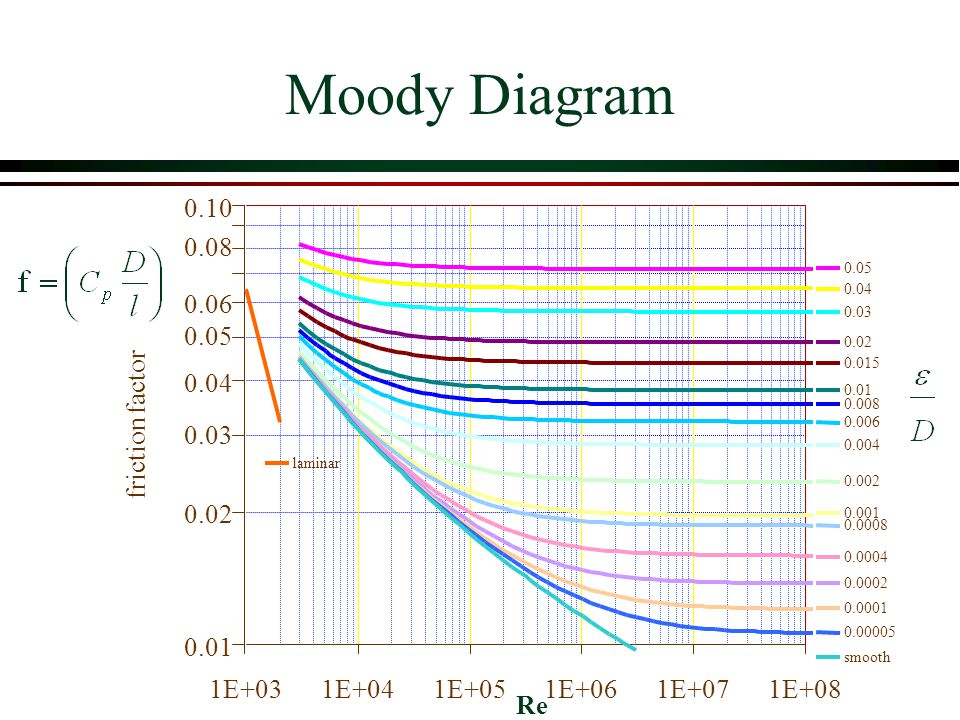
How to read the Moody Diagram By Dr. Sonya Lopez Moody Diagram @ First glance Three datasets in one graph On the left axis we have f, the friction factor On the right axis we have the relative roughness, roughness/diameter On the bottom axis we have Reynold's number Re = rho*velocity*diameter/mu REALLY IMPORTANT TO NOTE!
This photo about: How to Read A Moody Diagram, entitled as How To Read Moody Diagram - Vasodilator Stimulated Phosphoprotein How To Read A Moody Diagram - also describes How To Read Moody Diagram - Vasodilator Stimulated Phosphoprotein and labeled as: ], with resolution 3762px x 3468px
Moody chart (diagram) The Moody diagram is a chart showing the Darcy friction factor of a pipe as a function of the Reynolds number for selected roughnesses of the pipe wall. 1 Pressure loss. 1.1 Friction factor for laminar pipe flows. 1.2 Friction factor for turbulent pipe flows. 2 Moody chart.
Fig.1: Moody Friction Factor Diagram Image Source: Wiki. How to Read the Moody Diagram. Find out the curve most closely matching with your relative roughness value. For our example problem, we already found out the value of the relative roughness in Part-5 as 0.0075. So I will use the 6 th curve (0.01) from the top.
In Fluid Mechanics, the Moody chart or Moody diagram is a graph which relates the Darcy-Weisbach friction factor ( fD ) , Reynolds number (Re), and surface roughness for fully developed flow in a circular pipe. It can be used to predict pressure drop or flow rate down such a pipe.
The Moody chart or Moody diagram is a graph in non-dimensional form that relates the Darcy-Weisbach friction factor f D, Reynolds number Re, and relative roughness for fully developed flow in a circular pipe. It can be used for working out pressure drop or flow rate down such a pipe. Click on Chart image to get larger Moody Chart.
The Moody diagram is one of the things superseded by MS Excel. As Excel can't read charts, we use curve-fitting equations which approximate the Moody diagram's output. While this is an approximation, it might well be closer to the true experimental value than is read by the average person from an A4 copy of a Moody chart.










![How To Read A Moody Chart [6klz0mg9kv4g]](https://idoc.pub/img/crop/300x300/6klz0mg9kv4g.jpg)


0 Response to "45 how to read a moody diagram"
Post a Comment