42 skew-t diagram
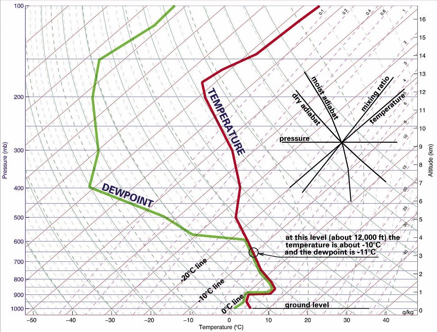
PDF skew t basemap3 - National Weather Service SKEW T ADIABATIC DIAGRAM 50° 40° 30° 20° 10° 0° -5° -10° -15° -20° -25° -30° -35° -40° -45° -50° 1 0.2 0.4 0.6 0.8 0 5 2.0 2.5 3 4 5 6 7 8 9 10 12 14 16 18 20 24 28 32 36 40 44 48 52 56 60 68 76 40 40 30 20 10 10 20 30 50 70 80 90 0 0 0 0 0 0 0 0 60 40 0 30 30 20 20 The Skew-T Diagram - University of Arizona The Skew-T Diagram The Skew-T diagram gives a "snapshot" picture of air temperature, dew point temperature, air pressure, and winds in the atmosphere above a particular point on the Earth's surface. The data is measured by launching hydrogen or helium filled balloons carrying weather instrument packages called
Mastering The Skew-T Diagram - PilotWorkshops The Skew-T diagram is one of the best kept secrets in aviation and one of the most versatile power tools in the pilot's preflight planning toolbox. Sure, there are plenty of tools and forecasts to give you a general picture of weather for your flight.

Skew-t diagram
Upper-Air page: RAL Real-Time Weather Upper-Air page: RAL Real-Time Weather. Winds/Temps at pressures: rawinsonde plot at 925 mb 850 mb 700 mb 500 mb 300 mb 250 mb 200 mb. including contours 925 mb 850 mb 700 mb 500 mb 300 mb 250 mb 200 mb. Skew-T/Log-P diagrams created from rawinsonde data. Introduction to the SkewT Diagram - NASA Introduction to the SkewT Diagram The SkewT diagram, more formally as the SkewT-LogP diagram, is a very useful meteorological thermodynamic chart on which pressure, density, temperature, and water vapor are plotted for a point on the Earth surface up through the atmosphere. NCL Graphics: SKEWT Since the program is plotting a skew-T log p diagram, the input NetCDF file should contain ADPUPA observational data from a valid synoptic observing station where radiosondes are launched, and that the input time is either 00 or 12Z (the synoptic times when radiosondes are launched). The DSS also provide IDL software to create a skewT.
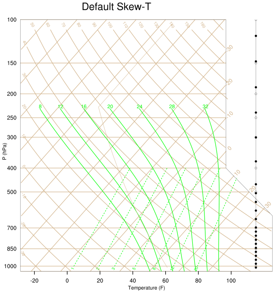
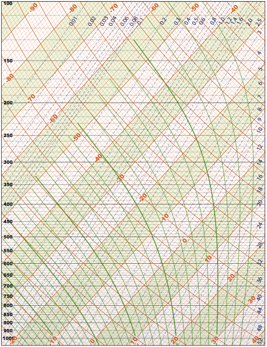
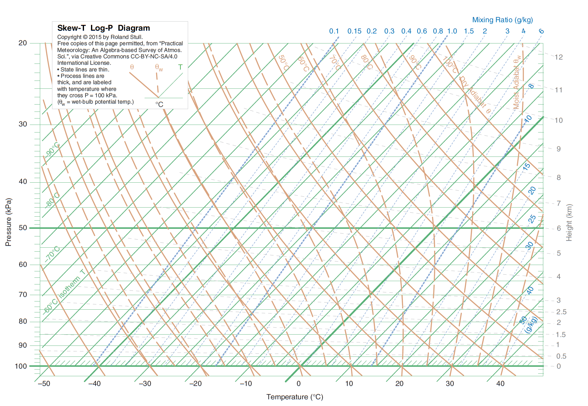
Skew-t diagram. Skew-t Basics Below are all the basics lines that make up the Skew-T Isobars-- Lines of equal pressure. left to right and are labeled on the left side of the diagram. Pressure is given in increments of 100 mb and ranges from 1050 to 100 mb. Notice the spacing between isobars increases in the vertical (thus the name Log P). 3.5 The Skew-T Diagram: A Wonderful Tool! | METEO 300: Fundamentals of Atmospheric Science The diagram has an electronic pen that allows you to draw on it. This diagram will be used in Practice Quiz 3-4 and Quiz 3-4, so become familiar with it. The most recent Skew-T Log-P diagram created from the radiosonde launched from Pittsburgh, PA. The date can be seen in the bottom left, and the time is in UTC time. Credit: NCAR NWS JetStream - Skew-T Plots - National Weather Service The five-digit coded radiosonde observation is complicated to decode and plot onto a Skew-T diagram. As such, there are several private weather vendors and universities who have written programs to decode and plot (or redisplay the info in a tabular format) these observations. PDF A GUIDE TO THE SKEW-T / LOG-P DIAGRAM - Luther College diagram. This plot is commonly called a 'sounding'. Sounding data come from weather balloons that are launched around the country at 00Z and 12Z, as well as various special situations in which they are used in field experiments and other campaigns. Figure 1 is an example skew-t-log P diagram. Figure 1: Skew-T - Log P Thermodynamic Diagram
Downloadable Skew-T diagrams for use with Downloadable Skew-T diagrams for use with A First Course In Atmospheric Thermodynamics. By Grant W. Petty. Color Skew-T in PDF format. Fits on 8.5x11 inch paper. 1050-100 mb-20 to +40 Celsius: B&W Skew-T in PDF format. Fits on 8.5x11 inch paper. 1050-100 mb-20 to +40 Celsius at surface. Sounding #1 (PDF format) for use in book exercises ... The Skew-T Diagram - University of Arizona The Skew-T Diagram The Skew-T diagram gives a "snapshot" picture of temperature, dewpoint, air pressure, and winds in the atmosphere above a particular point on the Earth's surface. The data is measured by launching hydrogen or helium filled balloons carrying weather instrument packages called radiosondes. As the balloon rises, the Skew-T charts for the UK - Netweather.tv The skew-t diagram is one of the key tools that many forecasters use to predict storm activity and many other weather phenomena. Until recently these diagrams could only be created by launching a balloon with a variety of instruments into the atmosphere. PDF Skew-t, Log-p Diagram Analysis Procedures The Skew-T, Log-P diagram is also considered a "pseudo-adiabatic diagram" in that it is derived from the assumption that the latent heat of condensation is used to heat the air parcel, and that condensed moisture falls out immediately. Similarly, the above assumption does not represent the observed changes which occur as air is lifted.
NOAA-19 POES Skew-T: US Continental Map - OSPO The POES Temperature and Moisture Soundings Profiles are displayed in Skew-T Log-P diagram format. These diagrams include both the POES and the first guess (model data). Also included are several derived parameters to the right of each diagram. The POES thermal gradient winds (derived from the Soundings) are also displayed on the diagrams. Wx Watch: Skew-T Basics - AOPA Skew-T diagrams can be useful elements. To be sure, there are shortcomings. Balloon launch stations are few and far between, leaving big gaps in data. The balloons are only launched twice a day, at 0000Z and 1200Z, and are quickly blown downwind of the launch site. This means data can be old, and irrelevant to conditions aloft at the launch ... GOES Skew-T Station List - OSPO GOES Skew-T Station List. INDEX: AZ AR CA CO FL GA HI ID IL IN IA KS KY LA ME MA MD MI MS MO MT NE NV NH NJ NM NC ND OH OK OR PA RI SC SD TN TX UT VT VA WA WV WI WY ATLANTIC OCEAN | PACIFIC OCEAN | GULF OF MEXICO CANADA | CARIBBEAN | MEXICO. The GOES-East satellite experienced an anomaly with the sounder, which is still being investigated. Only ... Sounding Analysis Archive - Storm Prediction Center Observed Sounding Archive. This page shows current and recent observed radiosonde data in skew-t format. An archive of seven days of data will always be available. The images are created using a sounding analysis program called NSHARP. Sounding data will flow to this site as early as HH:30 after the hour, and will also re-run old hours to fill ...
Skew T-log p diagram showing the temperature (right solid ...
How to use a Skew-T Log-P diagram - Air Facts Journal Let's get acquainted with a meteorological diagram called a Skew-T Log-P. This diagram's name stems from the fact that lines of equal temperature are skewed at a 45 degree angle along the horizontal axis and pressure in millibars is plotted on a logarithmic scale along the vertical axis.
Skew-T log (p) 101
Aerological Diagram — complex, but incredibly useful tool for weather forecasting at ... This diagram is also called Skew-t log-P diagram, where "Skew-T" comes from the fact that the temperature lines on the diagram from 1947 are skewed at a 45 degrees angle, and the "log-P" represents the "logarithm of the pressure", which shows how the atmospheric pressure decreases with increasing altitude.

Learn to Read a Skew-T Diagram Like a Meteorologist! In ...
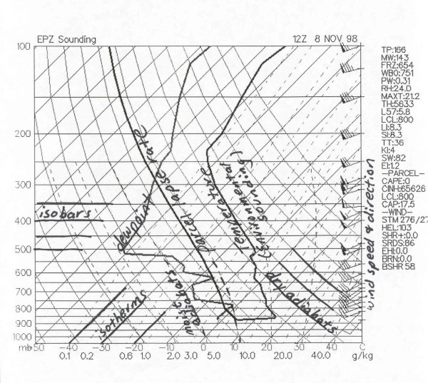
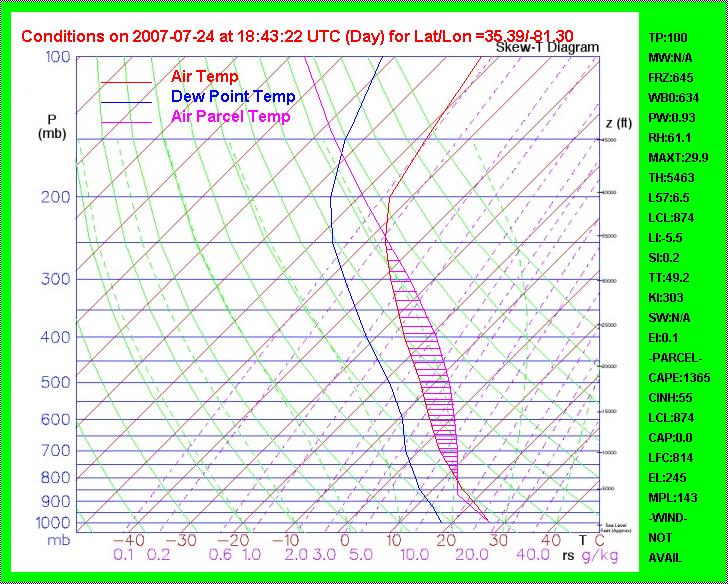
How To Read Skew-T Charts - WeatherTogether A Sample Skew-T Diagram. The slanted red lines are lines of constant temperature, the dotted purple lines are lines of constant mixing ratio, the solid curved green lines are dry adiabats, and the curved green lines are moist adiabats. The Lifting Condensation Level (LCL), Level of Free Convection (LFC), and Equilibrium Level (EL) are labeled.

Skew-T log-P diagram - Wikiwand
PDF Skew T's - How to Read Them The Skew-T diagram does double duty: It depicts by displaying lines - the calculations of the change in the temperature and dewpoint of a rising bubble in the absence of condensation, and the change in the temperature of a rising bubble where condensation is occurring - and it presents observed data.

Skew T examples
Forecasting Winter Weather with a Skew-T Diagram | Study.com A skew-T diagram is a special type of meteorological diagram that plots atmospheric pressure and temperature conditions as they change with height above ground level (the altitude). They provide ...
Skew-T Revisited - IFR Magazine
Skew-T log-P diagram - Wikipedia A skew-T log-P diagram is one of four thermodynamic diagrams commonly used in weather analysis and forecasting. In 1947, N. Herlofson proposed a modification to the emagram that allows straight, horizontal isobars and provides for a large angle between isotherms and dry adiabats, similar to that in the tephigram.It was thus more suitable for some of the newer analysis techniques being invented ...

How to use a Skew-T Log-P diagram - Air Facts Journal
PDF The skew-T log-P diagram - National Weather Service •The skew-T log-P diagram can depict a wide array of useful data and parameters using temperature, relative humidity and wind data gathered from a radiosonde. •Skew-T's help forecasters gage thunderstorm potential and tornado threat during convective events, and also help us determine precipitation type in winter-weather forecasting.

Determining the Planetary Boundary Layer Using a Skew-T ...
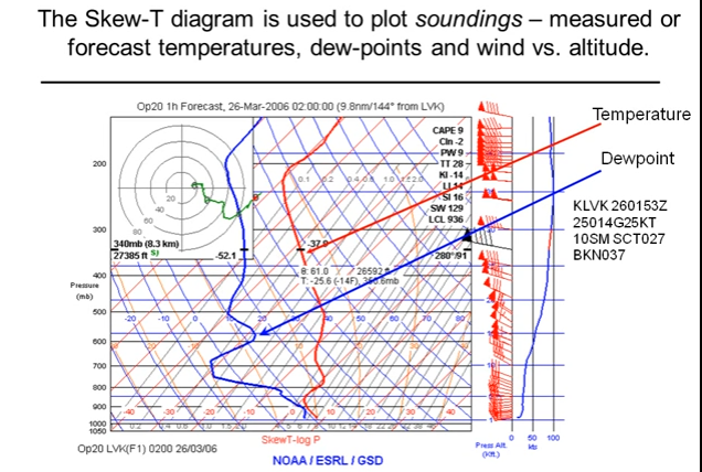
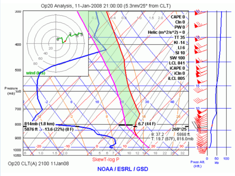
Skew-T Log-P Diagrams - National Weather Service Skew-T Log-P Diagrams The "Skew-T Log P" thermodynamic diagram used for plotting upper air observations. Once the radiosonde observation is plotted, the Skew-T will show the temperature, dew point, and wind speed/direction. From these basic values a wealth of information can be obtained concerning the meteorological condition of the upper air.

Airmass Thunderstorms
Determining Atmospheric Levels from a Skew-T Diagram - Study.com Skew-T plots are a very useful forecasting tool for meteorologists, as they can provide the user with a large amount of information on a single diagram. Let's examine four of the most common ...

Visual Explanation of Meteorological Skew T Log P Sounding Diagrams
Skew-T Parameters and Indices - National Weather Service Below are all the basics lines that make up the Skew-T: (Isobars)- Lines of equal pressure. the left side of the diagram. Pressure is given in increments of 100 mb and ranges from 1050 to 100 mb. Notice the spacing between isobars increases in the vertical (thus the name Log P). (Isotherms)- Lines of equal temperature.

NWS JetStream - Skew-T Log-P Diagrams
The Skew-T Thermodynamic Diagram - San Francisco State University One version of the thermodynamic diagram is the Stuve diagram, shown in our textbook. Another is the skew-T/log-P, or "skew-T" for short, so named because one of the primary axes of the graph (temperature) is skewed clockwise by 45°. It is harder to learn to read but a little more useful meteorologically. Stuve and Skew-T/Log-P Diagrams
Skew-t diagrams - PPRuNe Forums
NCL Graphics: SKEWT Since the program is plotting a skew-T log p diagram, the input NetCDF file should contain ADPUPA observational data from a valid synoptic observing station where radiosondes are launched, and that the input time is either 00 or 12Z (the synoptic times when radiosondes are launched). The DSS also provide IDL software to create a skewT.

Skew T Tutorial Part 1 Isotherms
Introduction to the SkewT Diagram - NASA Introduction to the SkewT Diagram The SkewT diagram, more formally as the SkewT-LogP diagram, is a very useful meteorological thermodynamic chart on which pressure, density, temperature, and water vapor are plotted for a point on the Earth surface up through the atmosphere.

The skew T-ln(p) diagram. The classic isolines of T , q v , θ ...
Upper-Air page: RAL Real-Time Weather Upper-Air page: RAL Real-Time Weather. Winds/Temps at pressures: rawinsonde plot at 925 mb 850 mb 700 mb 500 mb 300 mb 250 mb 200 mb. including contours 925 mb 850 mb 700 mb 500 mb 300 mb 250 mb 200 mb. Skew-T/Log-P diagrams created from rawinsonde data.
NCL Graphics: SKEWT
SkewTLogPro – Skew-T Log-P Charts For IPhone and iPad

The Skew-T Thermodynamic Diagram
3.5 The Skew-T Diagram: A Wonderful Tool! | METEO 300 ...

Skew T-logp diagram of the RCE soundings with five values of ...
Skew-T for the Common Pilot
Mastering The Skew-T Diagram - PilotWorkshops

Skew-T for the Common Pilot
A GUIDE TO THE SKEW-T / LOG-P DIAGRAM
Skew-T Thermodynamic Diagram Help | Jon Kahl
Skew-T Parameters and Indices

Original (modified) composite Skew-T log-p diagrams shown in ...
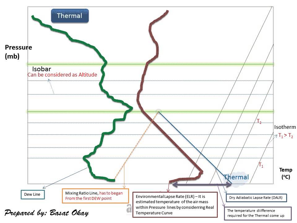
METEOROLOGY : Skew-T graphic, Thermal and Inversion

Nerdin' It Up: How to Find Instability by Hand on a SKEW-T Chart
Skew-T Parameters and Indices
Thermodynamic diagrams for free : eloquentscience.com
SKEW-T BASICS
Skew T's – How to Read Them

How To Read Skew-T Charts – WeatherTogether

Skew-T Description
Skew-T for the Common Pilot

Skew-T diagram @ Windy Community
Skew-T for the Common Pilot
Introduction to the SkewT Diagram
Mastering The Skew-T Diagram - PilotWorkshops

How to read a Skew-T Chart - for Soaring Pilots
Skew-T Log-P atmospheric sounding diagram - Q&A - GMT ...

NWS JetStream - Skew-T Log-P Diagrams
0 Response to "42 skew-t diagram"
Post a Comment