43 draw a top-down diagram of your setup from part e. this diagram should include
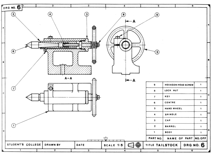
4. The left view should be drawn directly to the left of the front view. 5. The rear view should be drawn to the left of the left view or if necessary to the right of the right view. While some views can be omitted: no view should be drawn in any other position. Fig. 2-22 is a pictorial drawing of a simple piping sit- 1. (3.5) Draw a top-down diagram of your setup from part E. This diagram should include: a. The cardinal directions (N,S,E,W) b. The direction of current in the wires c. The direction of the compass needle d. A vector representing the Earth's magnetic field e. A vector representing the wire's magnetic field at the location of the compass f.
Draw a top down diagram of your setup from part e this diagram should include. You dont have to rely on your employees remembering the extra steps of saving and storing the diagrams in an appropriate and central location. In your mind draw a boundary around the fish tank including the waterto define it as your system.
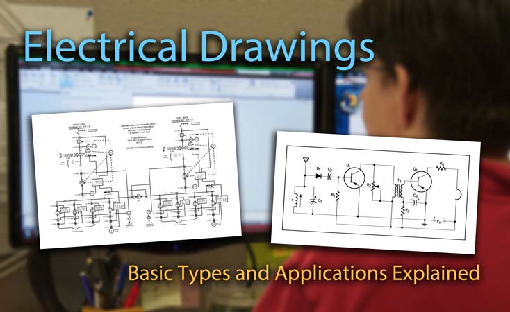
Draw a top-down diagram of your setup from part e. this diagram should include
(3.5) Draw a top-down diagram of your setup from part E. This diagram should include: a. The cardinal directions (N,S,E,W) b. The direction of current in the wires c. The direction of the compass needle d. A vector representing the Earth's magnetic field e. A vector representing the wire's magnetic field at the location of the compass f. 1. (3.5) Draw a top-down 2D diagram of your setup in part E (imagine looking from above). This diagram should include: a. The cardinal directions (N,S,E,W) b. The direction of current in the wires (8 for into, and O for out of the page) c. The direction of the compass needle (an arrow pointing to its north) d. The first step in describing and analyzing most phenomena in physics involves the careful drawing of a free-body diagram. Free-body diagrams have been used in examples throughout this chapter. Remember that a free-body diagram must only include the external forces acting on the body of interest. Once we have drawn an accurate free-body diagram ...
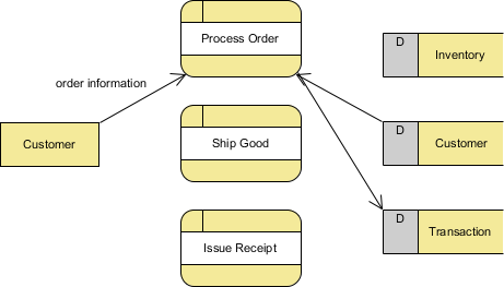
Draw a top-down diagram of your setup from part e. this diagram should include. Universally Accepted Terms. There are a few definitions used in network diagrams which you should be aware of. Activity: It is an operation which is commonly represented by an arrow (to show directions mostly) with an end as well as a starting point.. It can be of 4 types: Predecessor activity is to be completed before the start of another activity. ... This diagram should include: - The direction of current in the wires - The direction of the compass needle - Vectors representing the Earth's magnetic field and the magnetic field of the wire at the location of the compass - Known and relevant distances,angles, and currents - The cardinal directions (N,S,E,W) - Use your measurements from part E ... UML - Class Diagram. Class diagram is a static diagram. It represents the static view of an application. Class diagram is not only used for visualizing, describing, and documenting different aspects of a system but also for constructing executable code of the software application. Class diagram describes the attributes and operations of a class ... Step 1: Draw a Network Diagram Task 1, 4 days Task 2, 5 days Task 3, 3 days Task 4, 7 days Task 5, 4 days 0 4 4 9 14 18 4 7 147 Task 5 is dependent on Task 2 and Task 4 being complete. So, ES for Task 5 is 14 days (dependent on Task 4, which is the longer task. For forward pass, calculate the Early Start (ES) and Early Finish (EF).
The first step in describing and analyzing most phenomena in physics involves the careful drawing of a free-body diagram. Free-body diagrams have been used in examples throughout this chapter. Remember that a free-body diagram must only include the external forces acting on the body of interest. Once we have drawn an accurate free-body diagram ... 1. (3.5) Draw a top-down 2D diagram of your setup in part E (imagine looking from above). This diagram should include: a. The cardinal directions (N,S,E,W) b. The direction of current in the wires (8 for into, and O for out of the page) c. The direction of the compass needle (an arrow pointing to its north) d. (3.5) Draw a top-down diagram of your setup from part E. This diagram should include: a. The cardinal directions (N,S,E,W) b. The direction of current in the wires c. The direction of the compass needle d. A vector representing the Earth's magnetic field e. A vector representing the wire's magnetic field at the location of the compass f.


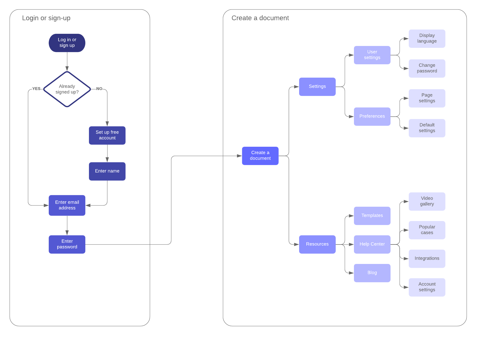


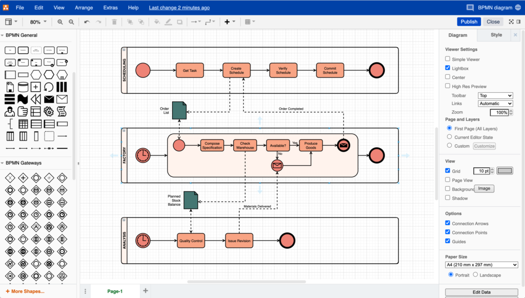

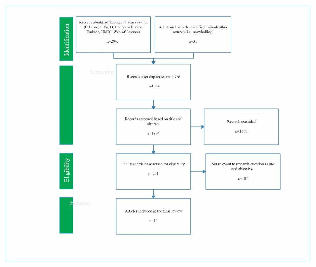


/dotdash_final_Range_Bar_Charts_A_Different_View_of_the_Markets_Dec_2020-01-98530a5c8f854a3ebc4440eed52054de.jpg)










:max_bytes(150000):strip_icc()/dotdash_Final_How_to_Draw_Fibonacci_Levels_Nov_2020-01-721becdc34264cceb240c7f755939d50.jpg)

0 Response to "43 draw a top-down diagram of your setup from part e. this diagram should include"
Post a Comment