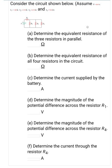
44 consider the circuit in the diagram below, in which r = 11 ω.
Figure 3.86. Circuit for Problem 10 11. Use the superposition principle to compute the voltage in the circuit of Figure 3.87. Answer: Figure 3.87. Circuit for Problem 11 RLOAD 135 w 12 A 18 A 4 Ω 6 Ω 12 Ω 15 Ω + − 36 V RLOAD iN = 0R, N = 23.75 Ω 4 Ω 5 Ω iX 15 Ω 5iX a b v18A 1.12 V 12 A 24 A 18 A + − 10 Ω-1 4 Ω-1 6 Ω -1 8 Ω ... The diagram below shows a circuit with three resistors. R,=4.082 R,=6.0.2 Rg. 160. A 9.0-volt battery is connected to a 4.0-ohm resistor and a 5.0-ohm ...4 pages
22.11 mW 4 101.75 9 4 101.75 , 1 2 max = 2 = Ω = = = R x V p V R Th Th Th Chapter 4, Solution 8. Let i = i1 + i2, where i1 and iL are due to current and voltage sources respectively. 6 ... For vo2, consider the circuit below. 6 Ω 5 ...

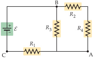
Consider the circuit in the diagram below, in which r = 11 ω.
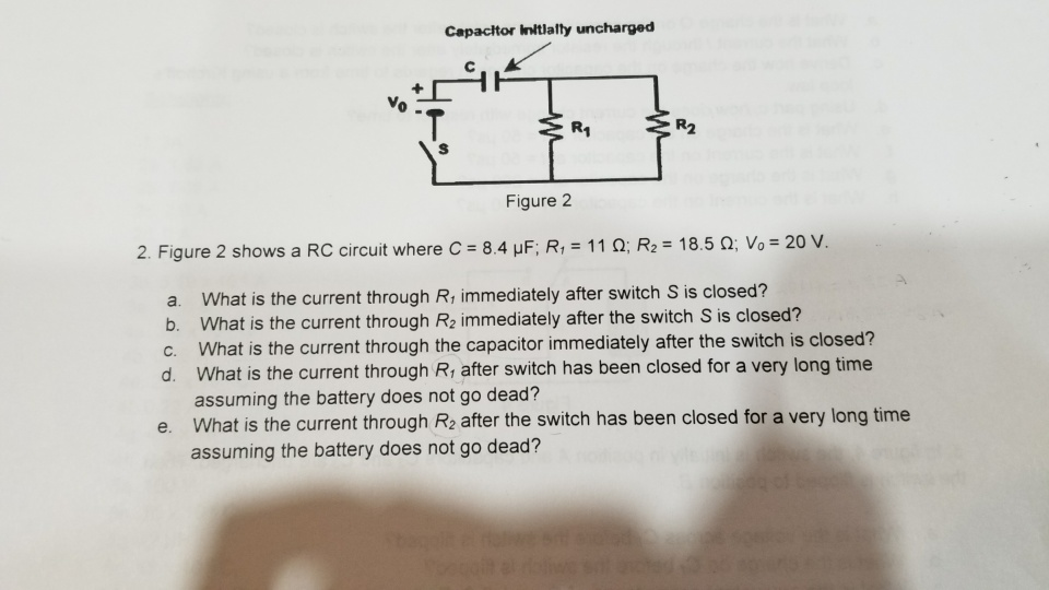
Questions 11-12 The above circuit diagram shows a battery with an internal resistance of 4.0 ohms connected to a 16-ohm and a ... 0.1 Ω (B) 10 Ω (C) 12 Ω (D) 120 Ω ... Consider the compound circuit shown above. The three bulbs 1, 2, and 3 - represented as resistors in the ... This circuit produces an output that is proportional to the input, that is v b = k v a where k is the constant of proportionality. (a) Determine the value of the output, v b, when R = 240 Ω and v a = 18 V. (b) Determine the value of the power supplied by the voltage source when R = 240 Ω and v a = 18 V. Consider a series RC circuit as in the figure below for which R = 1.00 MΩ, C = 5.00 µF, and ε = 30.0 V. Find (a) the time constant of the circuit and (b) the...
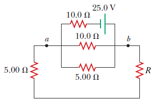
Consider the circuit in the diagram below, in which r = 11 ω.. Consider four circuit shown in the figure below. In which circuit power dissipated is greater (Neglect the internal resistance of the power supply) :- ... In the circuit shown in the figure, the heat produced it is the 5 Ω resistor due to the current flowing through it is 10 calories per second. Image: (B) The total resistance of the 3 Ω and 6 Ω in ... The five incomplete circuits below are composed of resistors R, all of equal resistance, ... Consider the circuit shown in Figure P21.29. Find(a)the current in the R 1 = 20 resistor and(b)the potential di erence between points aand b. R 3 10.0 V 25.0 V R 4 10.0 R 5 5.00 5.00 R 2 1 20.0 a b Label the voltage V = 25:0 V and the resistances (clockwise from b) R 1 = 20:0, R 2 = 5:00, R 3 = 10:0, R 4 = 10:0, and R 5 = 5:00. Computing some ... current-source circuit of the figure below to provide an output current I supply V CC =5V. Give the values of IREF For Vo=5V: 3. Find the output resistance of each of the two current sources below. Let R1=942k Ω, R2=9.3k Ω, R3=11.5k Ω, V Homework #2 REF =1mA, find IO when V o=5V. Also, find the output resistance. S=10-15 A, β=100, and V A ...
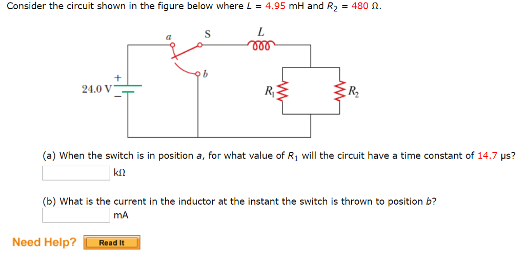
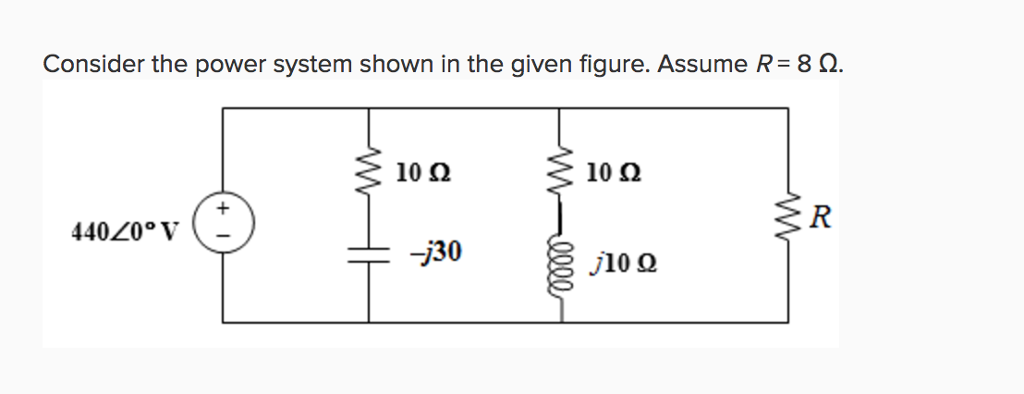
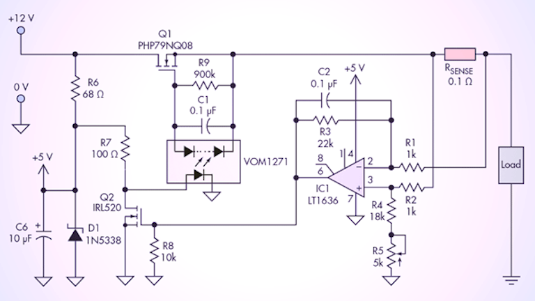
Example 4: High-pass RL filter A high-pass RL filter can be represented by the circuit in the figure below, with r being the internal resistance of the inductor. (a) Find V, the ratio of the maximum output voltage V to the maximum input voltage V. out,0 /Vin,0 in,0 out,0 (b) Let r =20.0 Ω, R=5.0 Ω, and L=250 mH.What is the frequency if ,0,0 Kim decides to design a circuit to control the light intensity of a portable lamp. The circuit consists of a 12-V light globe rated at 18 W, a variable resistor, a 12 V battery, and a 2 amp fuse with negligible resistance. Kim is considering two different circuits, shown as circuit A and circuit B. Figure 12.2.3 A purely inductive circuit As we shall see below, a purely inductive circuit corresponds to infinite capacitance and zero resistance . Applying the modified Kirchhoff's rule for inductors, the circuit equation reads C =∞ R =0 () L 0 L dI Vt Vt Vt L dt − =−= (12.2.11) which implies 0 L L sin dI Vt V t dt L L ==ω (12.2.12) Consider the circuit shown in Figure. The ac generator in tills circuit has an rms voltage of 65 V. Given that R = 15 Ω and L = 0.22 mH, find the rms current in this circuit in the limit of (a) high frequency and (b) low frequency. Solution: Chapter 24 Alternating Current Circuits Q.51P Consider the circuit shown in Figure.
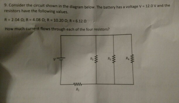
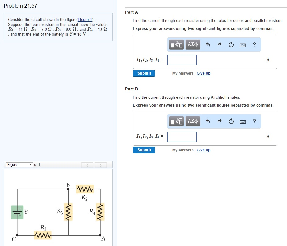
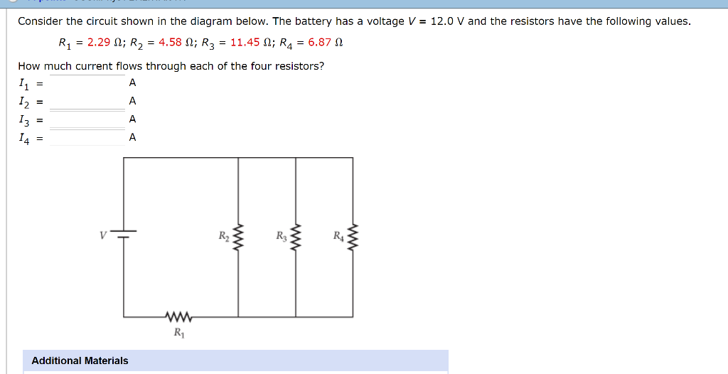
The radio has a. 3.20 Ω. 3.20 Ω resistance. (a) Draw a circuit diagram of the radio and its battery. Now, calculate the power delivered to the radio (b) when using a nicad cells, each having an internal resistance of. 0.0400 Ω. 0.0400 Ω, and (c) when using an alkaline cell, having an internal resistance of. 0.200 Ω. Consider the circuit shown in the diagram below. The battery has a voltage V = 12.0 V and the resistors have the following values. R1 = 2.32 2; R2 = 4.64 2, R2 = 11.60 2; R = 6.96 2 How much current flows through each of the four resistors? w RA ; Question: Consider the circuit shown in the diagram below. The battery has a voltage V = 12.0 V ... Then an understanding of the equivalent resistance of a series circuit can be used to determine the total resistance of the circuit. Consider the following diagrams below. Diagram A represents a combination circuit with resistors R 2 and R 3 placed in parallel branches. Two 4-Ω resistors in parallel is equivalent to a resistance of 2 Ω. R L ω ω ω == + c R L ω= A Serial RL Circuit Result ECE 307-4 22 Frequency Response of a Circuit Example Define R and L values for a high pass filter with a cutoff frequency of 10KHz. Find |H(jω)|at 5 KHz Let We can't calculate R and L values independently. We can select R or L values then define the other RK=Ω1 c R L ω = 1000 15.9 2 ...
Consider The Circuit In The Diagram Below In Which R 10 ω ...
R eq = R 1 + R 2 + R 3 = 17 Ω + 12 Ω + 11 Ω = 40 Ω. Now that the equivalent resistance is known, the current at the battery can be determined using the Ohm's law equation. In using the Ohm's law equation (ΔV = I • R) to determine the current in the circuit, it is important to use the battery voltage for ΔV and the equivalent resistance ...
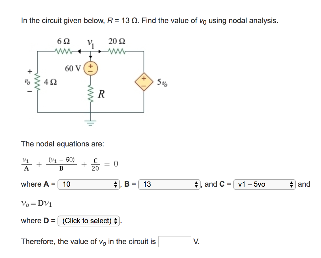
Consider The Circuit In The Diagram Below In Which R 13 ω ...
The total resistance of the circuit is R=Rbt+Rbulb=3.5 Ω + 19 Ω R=22.5 Ω The current through the 19-Ω resistor is I=VR=6 V22.5 Ω I=0.2667 A The voltage difference ΔVbulb across the 19-Ω resistor is calculated as follows: ΔV=5.0667 V
33 Consider The Circuit In The Diagram Below, In Which R ...
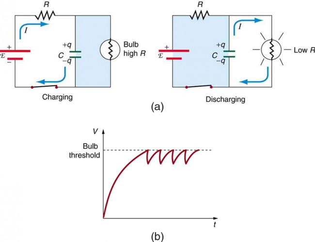
A circuit with resistance and self-inductance is known as an RL circuit. (a) shows an RL circuit consisting of a resistor, an inductor, a constant source of emf, and switches and When is closed, the circuit is equivalent to a single-loop circuit consisting of a resistor and an inductor connected across a source of emf ((b)). When is opened and is closed, the circuit becomes a single-loop ...
Solved: Consider The Circuit Shown On The Figure Below (Fi ...
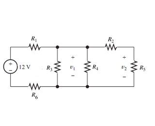
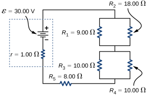
Oswal · 2021 · EducationR '; = R2 + R6 + R4 = ( 7 + 5 + 12 ) Ω = 24 Ω R ' and R5 are in parallel R'XR ... + 2 ) Ω = 11 Ω = Total resistance in circuit , + R = ( R " " '; + r ) = ( 11 ...
30 Consider The Circuit In The Diagram Below, In Which R ...
Z = 72.11 Ω * Eᵣ = Iₜ x R Eᵣ = 3.5 x 40 Eᵣ = 140 V * ... Consider the series circuit shown below. Drag the labels to the appropriate vectors on the correct vector diagram below. Er is adjacent, Ec is opposite, Et is hypotenuse. Using the circuit shown below, label the sides of the power triangle with the correct label and value. ...
Consider The Circuit In The Diagram Below In Which R 13 ω ...
PHY2054: Chapter 21 2 Voltage and Current in RLC Circuits ÎAC emf source: "driving frequency" f ÎIf circuit contains only R + emf source, current is simple ÎIf L and/or C present, current is notin phase with emf ÎZ, φshown later sin()m iI t I mm Z ε =−=ωφ ε=εω m sin t ω=2πf sin current amplitude() m iI tI mm R R ε ε == =ω
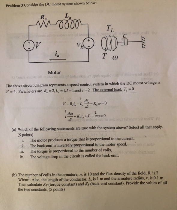
Solved: Problem 3 Consider The DC Motor System Shown Below ...
the circuit, but resistor reduction is a tool that we will use over and over. R 3 R 4 R 5 R 2 R 1 + - V S i S 1 kΩ 2.2 kΩ 330 Ω 470 Ω 1 kΩ To set the stage, consider the circuit at right. We might like to determine the power from the source, which requires knowing the current. Of course, we don't know the source current initially ...

30 Consider The Circuit In The Diagram Below, In Which R ...
= __1.64 Ω__ 7. Consider the circuit at the right. a. There is a voltage drop of __6__ V across each 2- resistor. ... 11. A 2-Ω and a 4-Ω resistor are connected in a parallel circuit. The current through the 4-Ω resistor will ... Use the diagram below at the right in order to answer questions.
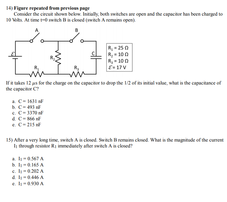
14) Figure repeated from previous page Consider the ...
In a space below draw a diagram showing all the elements connected in one electrical circuit that can provide the maximum rate of heat produced. Use two meters in your circuit, the y will help to measure the heat rate. The battery has an emf of 12 V and an internal resistance of 0.5 Ω and each heating 6. The diagram below shows a typical ...
Consider The Circuit In The Diagram Below In Which R 13 ω ...
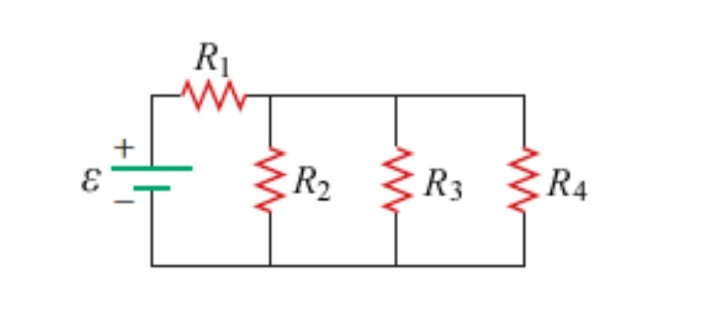
Give it a try. The resistors R 1 R 1 and R 2 R 2 are in series and can be reduced to an equivalent resistance. The same is true of resistors R 4 R 4 and R 5 R 5. But what do you do then? Even though this circuit cannot be analyzed using the methods already learned, two circuit analysis rules can be used to analyze any circuit, simple or complex.

Consider the circuit shown in the figure below. (Assume R1 ...
Example IV-1. Consider the circuit shown below, where R1 = 3.00 Ω, R2 = 10.0 Ω, R3 = 5.00 Ω, R4 = 4.00 Ω, and R5 = 3.00 Ω. (a) Find the equivalent resistance of this circuit. (b) If the total power supplied to the circuit is 4.00 W, find the emf of the battery. + − E R1 R2 R3 R4 R5 Solution (a): We have to reduce this circuit in steps ...

30 Consider The Circuit In The Diagram Below, In Which R ...
Consider the circuit shown in the diagram below. Consider the circuit shown in the diagram below for r1 5 ω r2 8 ω r3 8 ω r4 8 ω and v0 80 v. How much current flows through each of the four resistors. As sume the resistance of each light bulb remains constant. R 4 1050.

Solved: Consider The Circuit Shown In The Diagram Below, F ...
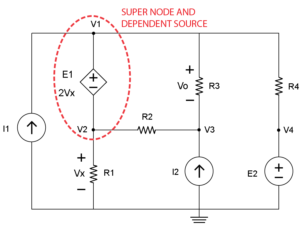
m m 6000 6000 3 16 16 3 v R R v + = ⇒= − (a) The voltage measured by the meter will be 4 volts when R = 6 kΩ. (b) The voltage measured by the meter will be 2 volts when R = 1.2 kΩ. P 4.3-9 Determine the values of the node voltages of the circuit shown in Figure P 4.3-9.. Figure P 4.3-9 . Solution: Express the voltage source voltages as functions of the node voltages to get
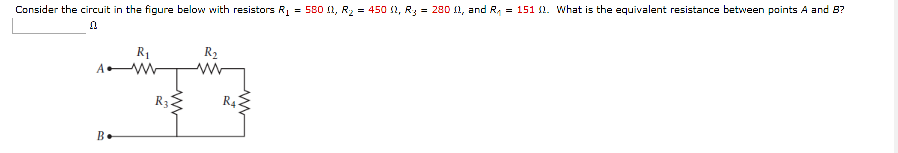
Solved: Consider The Circuit In The Figure Below With Resi ...
Base your answers to questions 11 through 13 on the information and diagram below. A 15-ohm resistor, R, and a 30-ohm resistor, R, are to be connected in ...11 pages
Solved: Consider The Circuit Shown In The Diagram Below. T ...
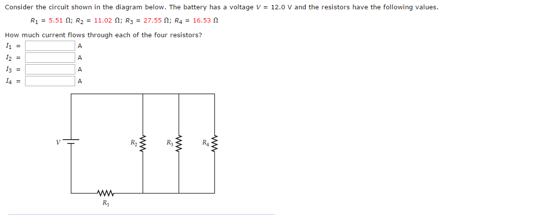
Physics questions and answers. Consider the circuit shown in the diagram below. The battery has a voltage V 12.0 V and the resistors have the following values R1 = 5.51 Ω; R2 = 11.02 Ω; R3 = 27.550; R4 = 16.53 Ω How much current flows through each of the four resistors? 12 = 13 14 = R3 R1.

Consider The Circuit In The Diagram Below In Which R 13 ω ...
Question: Consider the circuit in the diagram below, in which R = 11 ohm. (a) What is the resistance between points A and B? ______ Ohm(b) A 265-V emf is ...
.gif)
Physics B CFA 1 Review Quiz - Trimester 3 2014 - ProProfs Quiz
Consider a series RC circuit as in the figure below for which R = 1.00 MΩ, C = 5.00 µF, and ε = 30.0 V. Find (a) the time constant of the circuit and (b) the...
25 Consider The Circuit In The Diagram Below, In Which R ...
This circuit produces an output that is proportional to the input, that is v b = k v a where k is the constant of proportionality. (a) Determine the value of the output, v b, when R = 240 Ω and v a = 18 V. (b) Determine the value of the power supplied by the voltage source when R = 240 Ω and v a = 18 V.

Consider the circuit shown below. All three batteries are ...
Questions 11-12 The above circuit diagram shows a battery with an internal resistance of 4.0 ohms connected to a 16-ohm and a ... 0.1 Ω (B) 10 Ω (C) 12 Ω (D) 120 Ω ... Consider the compound circuit shown above. The three bulbs 1, 2, and 3 - represented as resistors in the ...
Consider The Circuit In The Diagram Below In Which R 13 ω ...
Solved: Consider The Circuit Shown In The Figure Below Whe ...
30 Consider The Circuit In The Diagram Below, In Which R ...
30 Consider The Circuit In The Diagram Below, In Which R ...
Solved: Consider The Circuit Shown Below (assume E= 9v, R1 ...
34 Consider The Circuit In The Diagram Below In Which R 10 ...
33 Consider The Circuit In The Diagram Below, In Which R ...
34 Consider The Circuit In The Diagram Below In Which R 10 ...
Physics Archive | February 13, 2017 | Chegg.com
Solved: Consider The Circuit Shown In The Diagram Below. T ...
30 Consider The Circuit In The Diagram Below, In Which R ...
Solved: Consider the circuit below. The battery has an emf ...

A circuit is setup by connecting inductance l=100mh ...
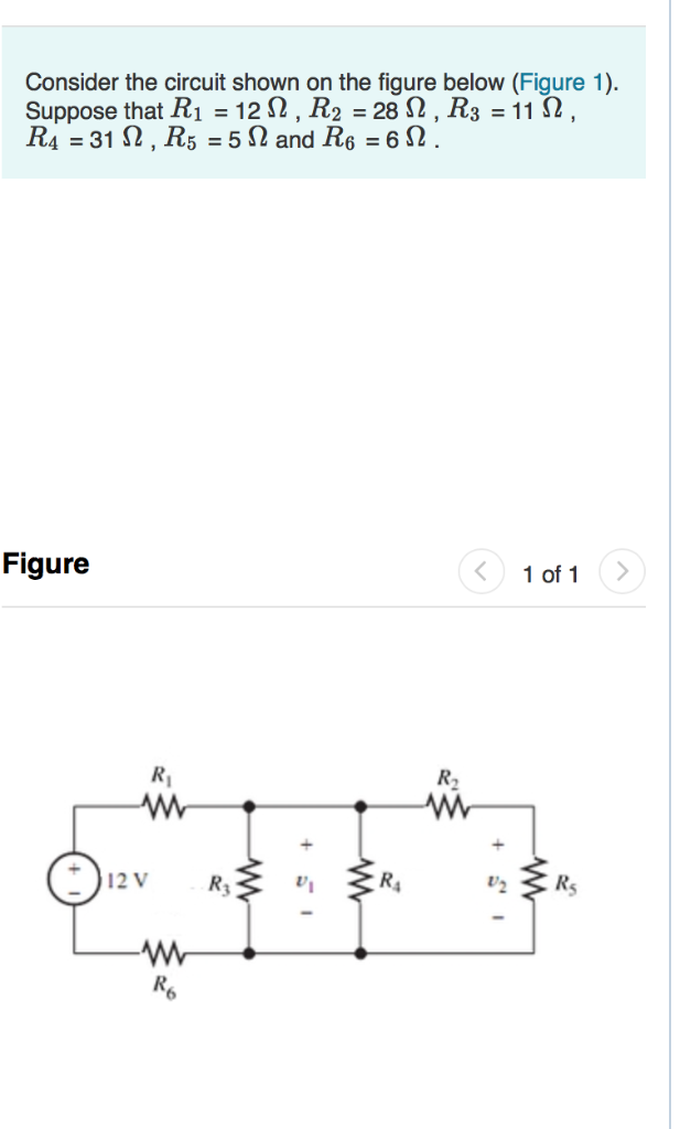
Solved: Consider The Circuit Shown On The Figure Below (Fi ...
29 Consider The Circuit In The Diagram Below, In Which R ...
Solved: Consider The Circuit Shown Below (assume E= 9v, R1 ...
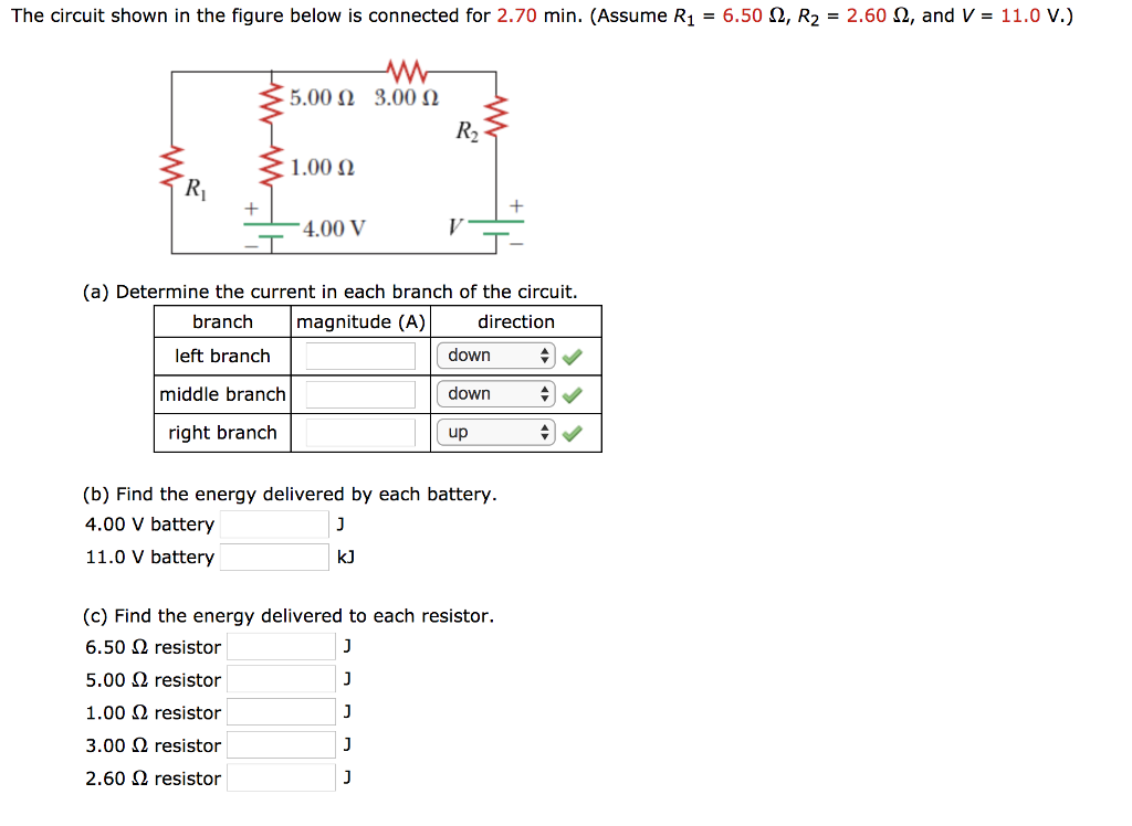
Solved: The Circuit Shown In The Figure Below Is Connected ...
Consider The Circuit In The Diagram With Sources Of Emf ...
Consider the circuit shown below. Suppose ... | Clutch Prep

Consider The Circuit In The Diagram Below In Which R 11 ω ...
30 Consider The Circuit In The Diagram Below, In Which R ...

34 Consider The Circuit In The Diagram Below In Which R 10 ...
![Star to Delta Conversion MCQ [Free PDF] - Objective ...](https://storage.googleapis.com/tb-img/production/18/03/1106.PNG)
Star to Delta Conversion MCQ [Free PDF] - Objective ...
Solved: Consider The Circuit Shown In The Figure Below. (L ...
Solved: Consider The Circuit Shown Below. (a) Determine Th ...
0 Response to "44 consider the circuit in the diagram below, in which r = 11 ω."
Post a Comment