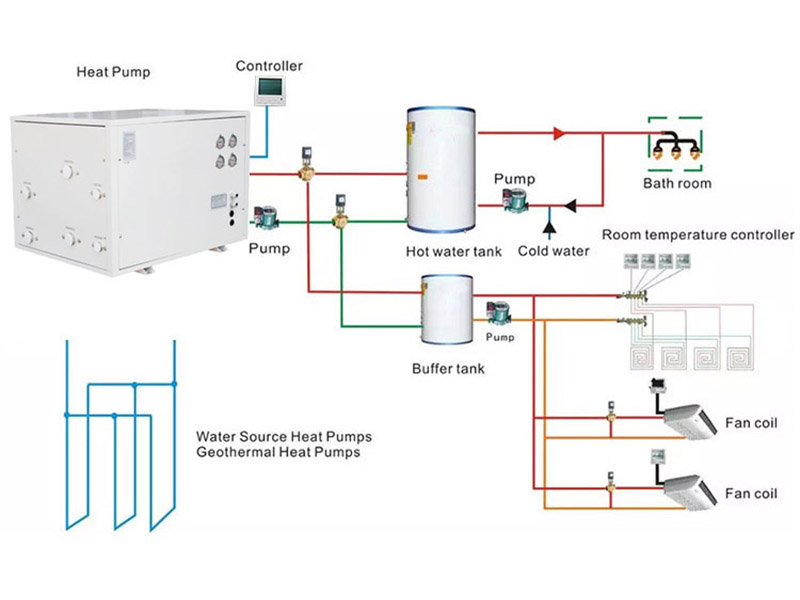
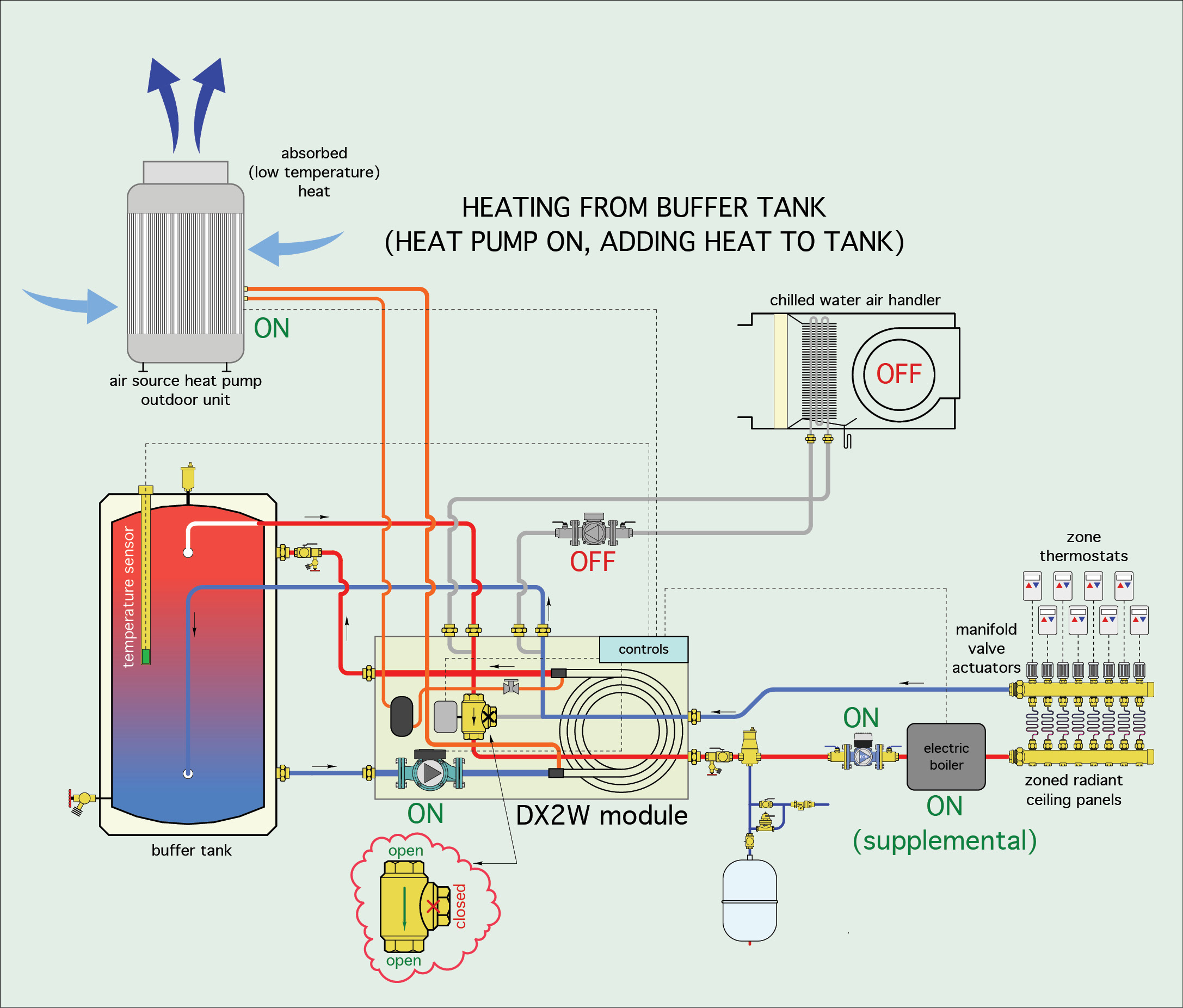
45 water source heat pump piping diagram
The Closed Water Loop Heat Pump System has gained wide acceptance among owners and designers to the point where it is the preferred system for multi-room or multi-zone buildings. For example, a U.S. Department of Defense directive states, “The most efficient method of using elec-tric power for heating is the water source heat pump… Ac- from one medium to another. A water source heat pump extracts heat from the water when in the heating mode and rejects heat to the water when in the cooling mode. The water supply may be a recirculating closed loop or a once-thru system using water from a well, a pond, or a stream. Water for closed-loop heat pumps is usually circulated at 2.25 ...
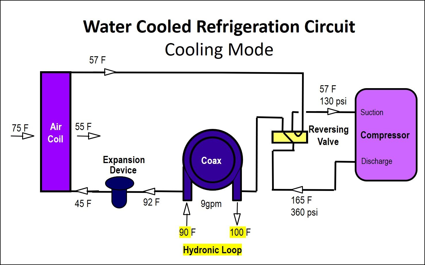
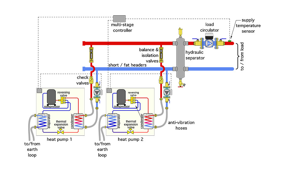
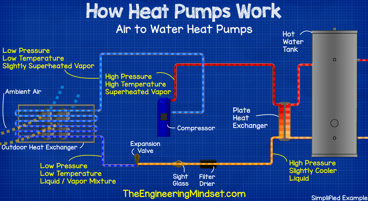
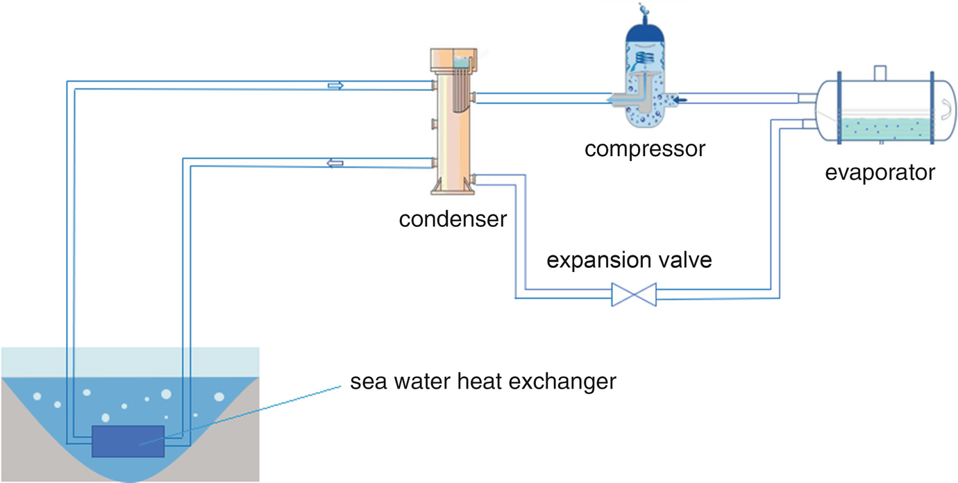
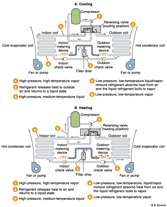
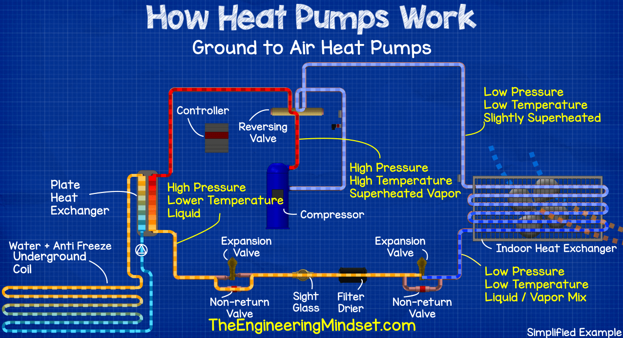
Diagram Of Heat Pump System - Introduction To Water Source Heat Pump Systems Part 3 Basic Operation : Heat engines, heat pumps, refrigerators, and air conditioners are examples of such systems.. There are many different types of heat pumps and are classified by the jobs they are to do as well as how they are designed to do these jobs.

Water source heat pump piping diagram
In a series circuit, the simplest hydronic piping system, the radiators and boiler are on one common loop. Radiators near the end of the loop are often larger to compensate for the lower water temperature. In the simplest hydronic distribution system, all heat emitters are connected into a common loop, or “circuit,” with the heat source. Water Source Heat Pump Units A water source heat pump is a self-contained water-cooled packaged heating and cooling unit with a reversible refrigerant cycle. Its components are typically enclosed in a common casing, and include a tube-in-tube heat exchanger, a heating/cooling coil, a compressor, a fan, a reversing valve and controls. PIPING ACCESS TO THE UNIT Water piping to and from the unit enters the unit casing through the water access panel. Piping connections are made directly to the heat exchanger coil and are 3/4" or 1" FPT. The access panel can be installed on the front of the unit (as received) or on the right side of the unit.
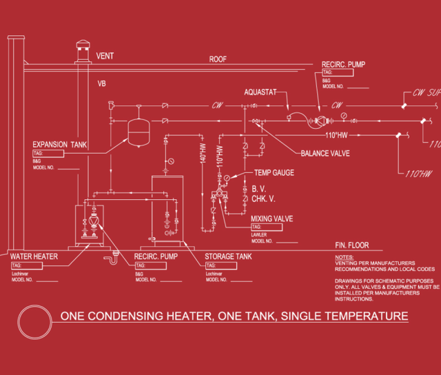
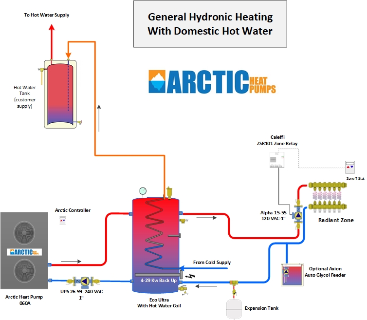
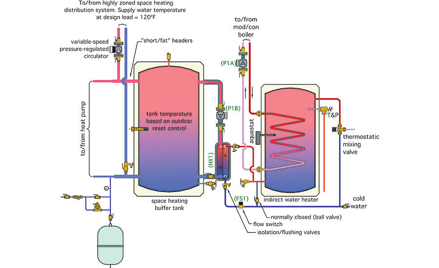
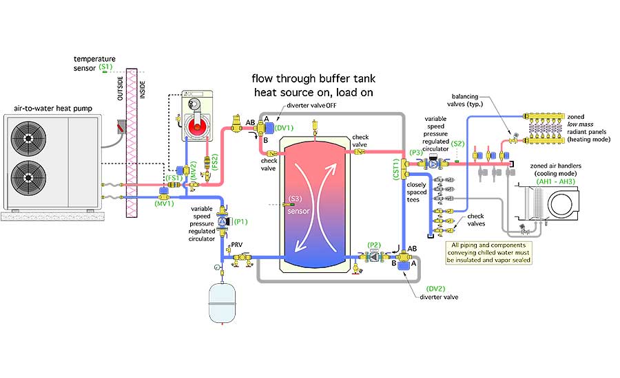
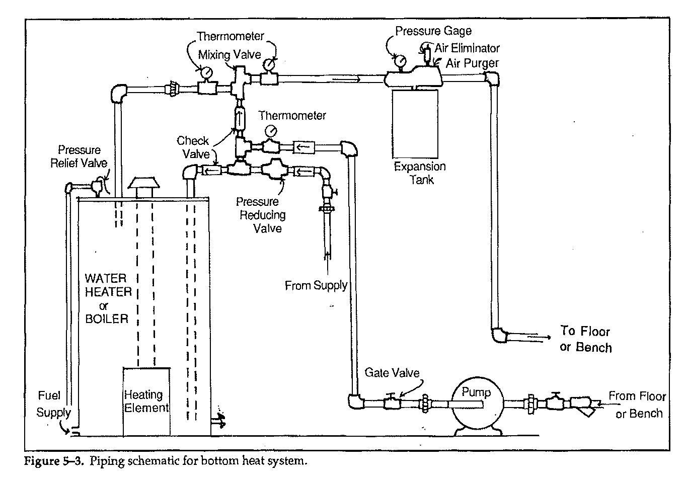
Water source heat pump piping diagram. 4. The minimum pipe size for connecting to a water storage tank is 1 ½”. 5. The minimum pipe size for connecting the boiler is 1 ½” for the Mod Con 300 VWH and 2” for the 500 and 850 models. 6. All pumps are shown with isolation flanges or full port ball valves for isolation. The alternative is standard flanges with full port ball ... • Diagram typical piping hookups for chillers, pumps, and cooling towers • Size the piping for a closed loop and an open recirculating loop system • Identify the types of water pumps, their features, and the selection process Section 1 – Introduction 3.3.1. Colmac HPW water-source heat pump water heaters can be used effectively when the building has both central water heating and central air-conditioning. 3.3.2. Piping connecting HPW heat pumps to storage tanks is identical to HPA heat pumps and is as shown in the diagrams below. 3.3.3. S = Source Side Cupro Nickel Coax B = Load & Source Side Cupro Nickel Coax Desuperheater 14 20 Y = None D = Waste Heat Recovery Water Heater Refrigerant 15 21 A = R-410A Cabinet Electrical 22 YYY= Reserved for future use www.DaikinApplied.com3WRA, WHA, WCA WATER TO WATER WSHP • IM 1072-4
PIPING ACCESS TO THE UNIT Water piping to and from the unit enters the unit casing through the water access panel. Piping connections are made directly to the heat exchanger coil and are 3/4" or 1" FPT. The access panel can be installed on the front of the unit (as received) or on the right side of the unit. Water Source Heat Pump Units A water source heat pump is a self-contained water-cooled packaged heating and cooling unit with a reversible refrigerant cycle. Its components are typically enclosed in a common casing, and include a tube-in-tube heat exchanger, a heating/cooling coil, a compressor, a fan, a reversing valve and controls. In a series circuit, the simplest hydronic piping system, the radiators and boiler are on one common loop. Radiators near the end of the loop are often larger to compensate for the lower water temperature. In the simplest hydronic distribution system, all heat emitters are connected into a common loop, or “circuit,” with the heat source.









.png)




0 Response to "45 water source heat pump piping diagram"
Post a Comment