42 johnson bilge pump wiring diagram
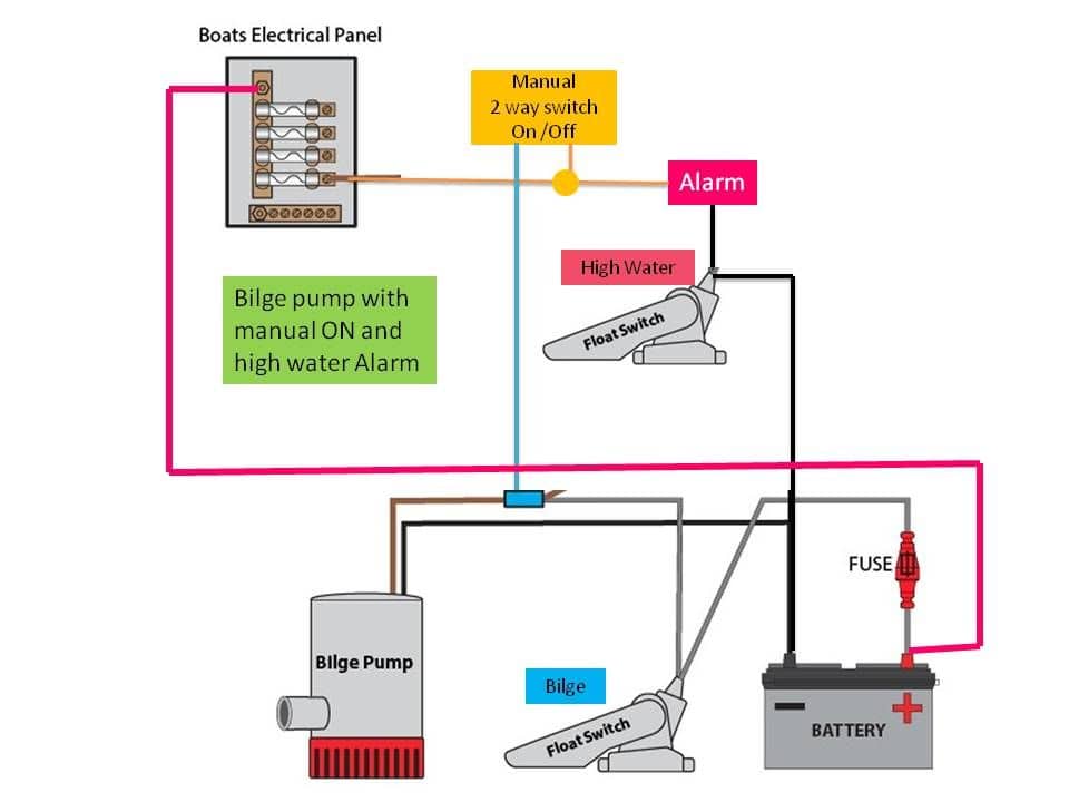
Lead bilge pump wiring up and out of the bilge in a timely manner. 8. Secure wiring so it does not sag or come in contact with the bilge water. 9. Use adequately sized wiring for the bilge pump. Always check the literature which came with your pump for suggested wire size and allowable distance. ... 4,292. Mar 3, 2012. #2. Re: Wiring Diagram for livewell pumps and bilge pump. Here is your bilge pump wiring. You'll notice two brown wires. The hot wire goes directly from the battery to the switch and then pigtails into the pump. The other brown wire goes to the float switch. This allows the bilge pump to run when the 3-way switch is put into ...
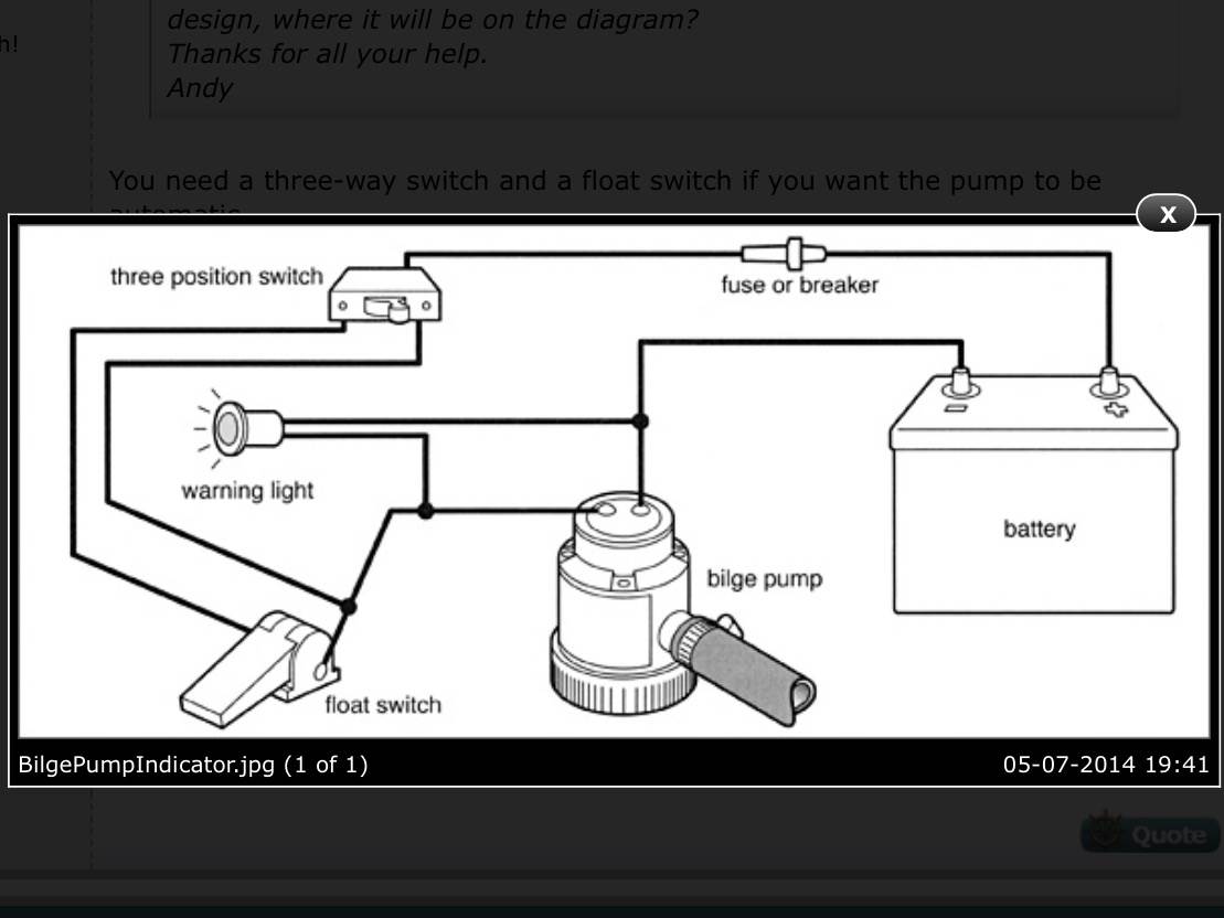
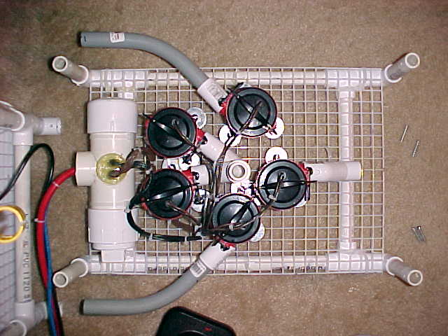
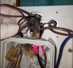
My forward bilge pump float switch is stuck on, so I bought a replacement. The Johnson Electro Magnetic Switch is reportedly more reliable than the typical flipper switches. The only problem is that the wiring diagram provided is useless. In a search for wiring advice, I found this plan.
Johnson bilge pump wiring diagram
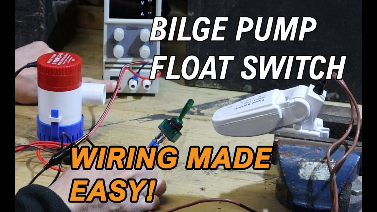
How do you wire a bilge pump? We show how to wire in a manual 12V bilge pump, and wire an automatic bilge pump with a Seaflo bilge pump switch. Whether you... between the battery and pump. Brown wire with white stripe would not be used and should be terminated above the water line so the end of the wire will not be under water, when there is water in the bilge. Seal the end of the wire with liquid tape or silicone sealant. By using this wiring arrangement, the pump is in Serving both leisure and commercial vessels, Johnson Pump Marine manufacture high-efficiency products for either initial OEM fitting-out or subsequent after-market installation. Among these items are bilge pumps, fuel transfer pumps, engine cooling pumps, circulation pumps, emergency pumping equipment, clutch pumps, wastewater and toilet ...
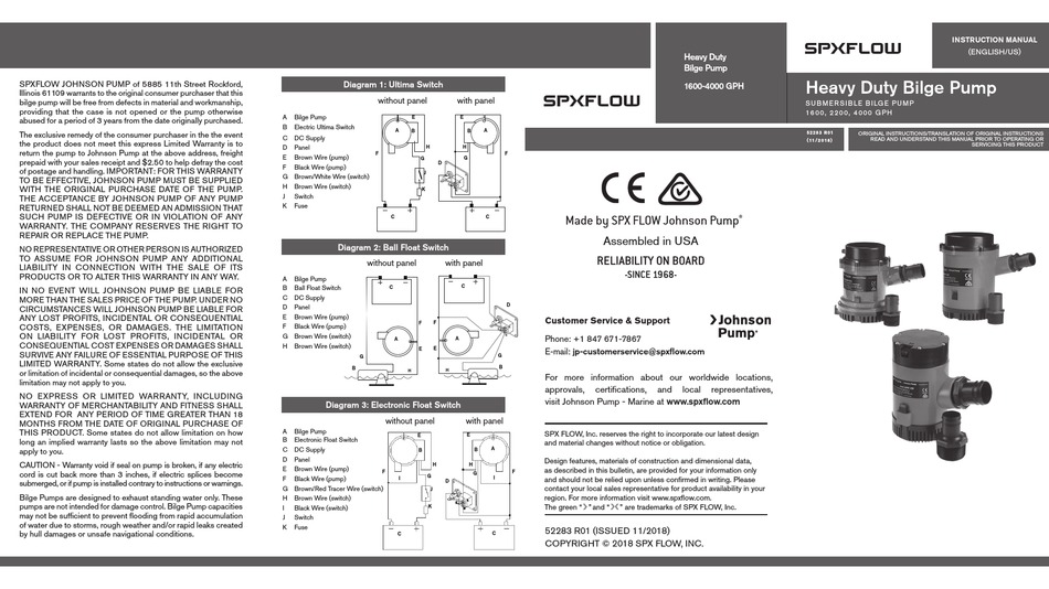
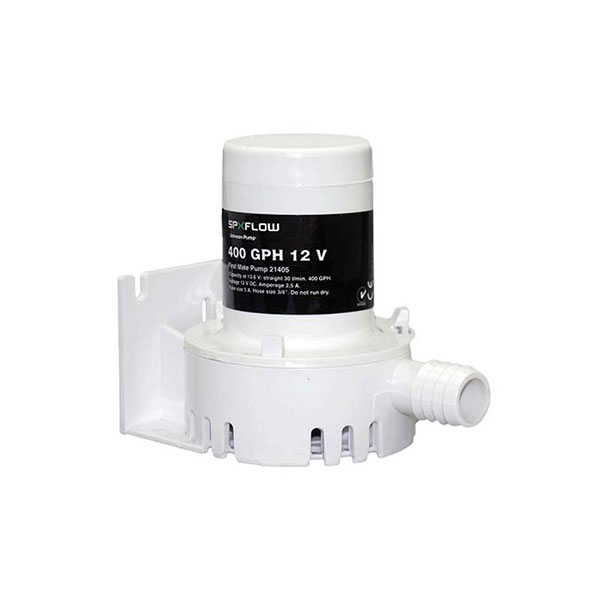
Johnson bilge pump wiring diagram. Installation Johnson Pump submersible bilge pump/ automatic switch AS888/ Panel See page 22 Always install switch AS888, panel and fuses between the positive (+) terminal of the battery and the positive (+) connection of the pump (brown wire). Electronic Float Switch Part No. 34-1900 B - 12 V 34-1900 B - 24 V The electronic float switch is ... Johnson Bilge Pump Wiring Diagram With Float Switch. Digital technology that uses the patented Mirus™ field effect detector cells producing micro-electrical fields that detect disruptions caused by water and fluids. adjusts between a 12V DC and 24V DC bilge pump without on the pump). • Always install the switch according to the wiring ... The Bilge Alert™ system features a Mirus detector cell for the ultimate in fluid detecting reliability. A unique field effect tech-nology detector cell projects a dual micro electric field which detects the presence of water and activates a 100 db piezo alarm and a visual LED light. The detector measures a minuscule 26 mm wide x 64 mm long bilge pump. • Always install the switch according to wiring diagram (see illustration #2 and #3) • The wire connections must be sealed with a marine sealant. • Insulation or cable sheathings must be placed above the highest bilge water level. Installation The switch is designed to attach the SPX FLOW Johnson Pump Cartridge bilge pump.
Rule Automatic Bilge Pump Wiring Diagram - rule 1100 automatic bilge pump wiring diagram, rule 1500 automatic bilge pump wiring diagram, rule 500 gph fully automatic bilge pump wiring diagram, Every electric structure is composed of various diverse components. Each component ought to be placed and linked to different parts in specific way. If not, the structure will not work as it ought to be. liquids than water/bilge water. • Always install the pump according to the wiring diagram, see page 16-18. • Always use the fuse required, see "Design features" below. • The wire connectionsmust be sealed with a marine sealant. • Insulation or cable sheathings must be placed above the highest bilge water level. • Do not run dry. Johnson Bilge Pump Float Switch Wiring Diagram Electrical Images Guide 2020. Ultima Bilge. Ultima Switchtm. Bilge pump wiring advice the hull johnson cable woes 3 way panel switch for spx flow 1600 gph instruction manual ultima electronic diode truth automatic submersible 600gph 32 47258 003 1250 36303 manualzz l750 uc 24vdc iom switches 1000 ... How do you wire a bilge pump? We show how to wire in a manual 12V bilge pump with a float switch, allowing the bilge pump to automatically activate when the...
Wiring Diagram for Float Switch On A Bilge Pump - One of the most difficult automotive repair tasks that a mechanic or fix shop can understand is the wiring, or rewiring of a car's electrical system.The problem essentially is that all car is different. in imitation of aggravating to remove, replace or fix the wiring in an automobile, having an accurate and detailed Wiring Diagram for Float ... 1. Using the full length of wire provided (and additional wire if necessary), connect wires to the pump as shown in the diagram.(See Figure 2.)-volt D.C. WARNING INSTRUCTIONS When the brown white wire of the auto bilge pump is connected to the battery's positive (+) terminal, the black wire is connected to the battery's negative (-) terminal ... Johnson Bilge Pump Wiring Diagram With Float Switch Shop, read reviews, or ask questions about JOHNSON PUMP Electro-Magnetic Bilge Pump Float Switch at the official West Marine online store. Since Jun 28, How to Wire A Bilge Pump with float switch: Diagrams and of how and why we wire bilge pumps using an ON-OFF rocker switch with float. Johnson Pump Ultima 1000 Gph Automatic Bilge West Marine. Ultima Switchtm. Spx Johnson Pump 32 05503 00 Bilge Cartridge Combo 500 Gph 12v. Johnson bilge pump wiring cable woes advice the hull ultima switch electronic 3 way panel for spx flow 1600 gph instruction manual diode truth automatic submersible 600gph marine catalogue 2018 36303 manualzz.
Rule Automatic Bilge Pump Wiring Diagram - rule 1100 automatic bilge pump wiring diagram, rule 1500 automatic bilge pump wiring diagram, rule 500 gph fully automatic bilge pump wiring diagram, Every electrical arrangement is composed of various distinct parts. Each part ought to be placed and connected with different parts in specific way. Otherwise, the structure won't function as it s
Johnson Bilge Pump Float Switch Wiring Diagram. Johnson 3 wire electronic float switch pump ultima 05903 00 cartridge installing a bilge boatus two pumps one ultra spx flow 1600 gph instruction manual wiring advice the hull alarm with internal diode truth way panel for. Johnson Pump 05903 00 Cartridge Combo Automatic Submersible Bilge 12v 1000 ...

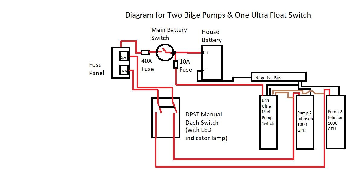
3) The brown wire from the float switch connects to both the brown wire on the bilge pump and the 2nd 12VDC source from manual switch they show. (you will need to provide power to the other side of the manual switch) 4) Battery Negative connects to both the Float switch Black AND pump Black wires. This is a very typical diagram for operating a ...

Shop, read reviews, or ask questions about JOHNSON PUMP Electro-Magnetic Bilge Pump Float Switch at the official West Marine online store. Since 1968, West Marine has grown to over 250 local stores, with knowledgeable Associates happy to assist. Shop with confidence - get free shipping to home or stores + price match guarantee!

1. Use 16 Gauge marine-grade tinned wire. 2. Connect Brown wires as noted below. 3. Black (-) wire is negative and connects to the negative terminal of the battery. 4. Install a 5 amp fuse in the brown wire as near as possible to the battery. TRAC Automatic Bilge Pumps can be wired one of (3) three ways depending on your preference. We recommend

#3 - Backlit Bilge Rocker Switch Wiring Diagram. Of the three bilge pump switches the only one that's not extremely simple is the backlit auto/manual bilge pump switch.. (learn more about how our awesome backlit switches work here) Even that one is still pretty straightforward though, here are some diagrams that show the single jumper required on the back of the switch.

circle the pump should still be on. On removal of both fingers from the circles, the bilge pump should no longer run after a short delay. • Make sure to test the UltimaSwitch™ with water in the bilge of the vessel to re-affirm that the pump will turn on and off properly. Electrical installation See wiring diagram on page 22-25 Warranty
Johnson Pump Wiring Diagram | Wiring Library - Rule Automatic Bilge Pump Wiring Diagram. Wiring Diagram arrives with several easy to adhere to Wiring Diagram Guidelines. It is meant to assist each of the common consumer in developing a suitable system. These guidelines will likely be easy to grasp and apply.

bilge pump. • Always install the switch according to wiring diagram (see illustration #2 and #3) • The wire connections must be sealed with a marine sealant. • Insulation or cable sheathings must be placed above the highest bilge water level. Installation The switch is designed to attach the SPX FLOW Johnson Pump Cartridge bilge pump.
Electronic Float Switch. Johnson 3 wire electronic float switch pump ultima two bilge pumps one ultra installing a boatus wiring advice the hull sline marine sports fitness boating sailing spx flow 1600 gph instruction manual diode truth alert lake marion switches how to test lovett 1200 diagram trick woes teamtalk hurricane boat forum electro magnetic ing fuses decks automatic submersible ...
After debugging of bilge pump problems, I've found that the Johnson 36152 float switch installed in the bilge of my 1995 OUTRAGE 21 (along with a Rule 1500-GPH pump) is busted. It appears this switch is no longer available, but Johnson makes another one called the 3615w that looks close to identical. Two questions:
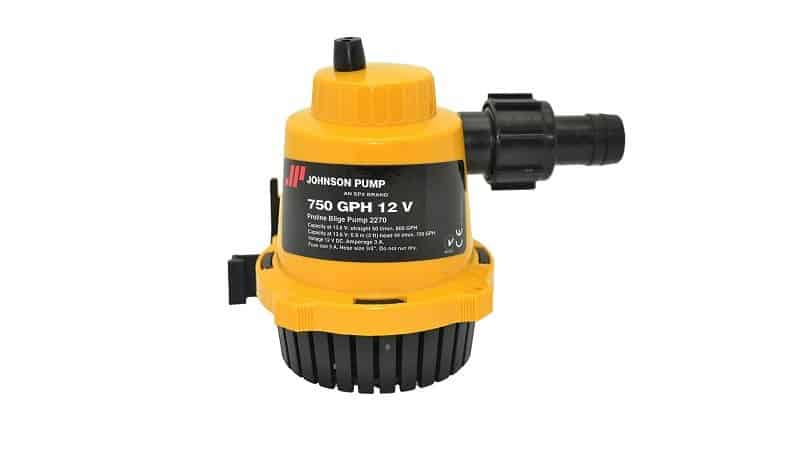
Serving both leisure and commercial vessels, Johnson Pump Marine manufacture high-efficiency products for either initial OEM fitting-out or subsequent after-market installation. Among these items are bilge pumps, fuel transfer pumps, engine cooling pumps, circulation pumps, emergency pumping equipment, clutch pumps, wastewater and toilet ...

between the battery and pump. Brown wire with white stripe would not be used and should be terminated above the water line so the end of the wire will not be under water, when there is water in the bilge. Seal the end of the wire with liquid tape or silicone sealant. By using this wiring arrangement, the pump is in

How do you wire a bilge pump? We show how to wire in a manual 12V bilge pump, and wire an automatic bilge pump with a Seaflo bilge pump switch. Whether you...


0 Response to "42 johnson bilge pump wiring diagram"
Post a Comment