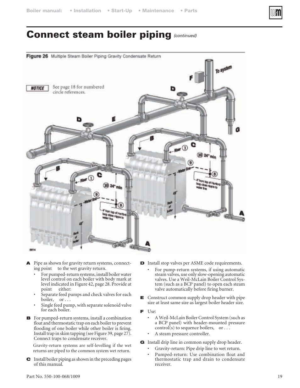
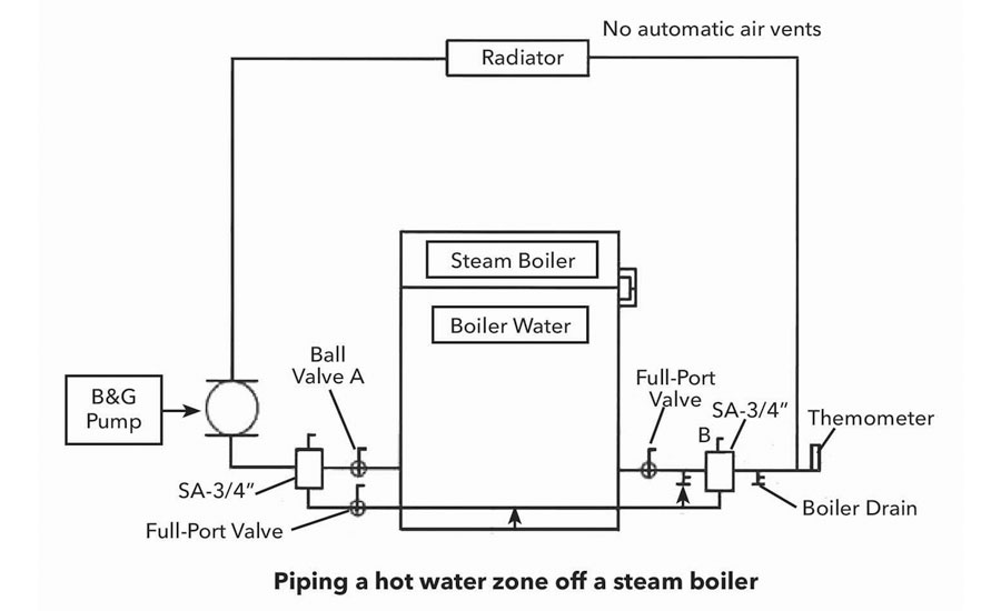
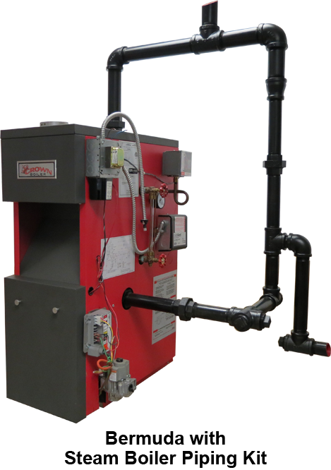
44 steam boiler piping diagram
Therefore, propane boilers, piping, valves should NOT be installed in locations where propane leaking from defective equipment and piping will "pool" in a basement or other space below the leak. A spark or flame from the boiler or other source may ignite the accumulated propane gas causing an explosion or fire.
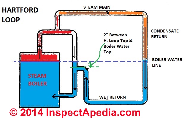
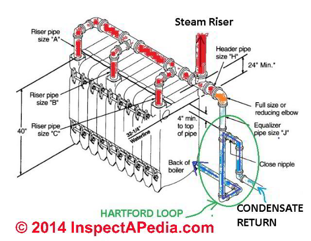
The primary component of a Hartford loop diagram is the location of a Hartford loop top and its distance from the boiler water top. Standard Hartford loop diagrams generally place the top of the loop 2 inches below the steam boiler's water line. hartford loop steam piping diagram is among the photos we discovered on the net from reputable sources.
Most of the wiring diagrams are for natural gas powered steam boilers. Wiring diagrams for oil burning and water boilers are noted. CT 6, 10, 15 and 25 boiler wiring diagram CT 6 and 25 boiler wiring diagram CT 35 and 50 boiler wiring diagram HRT 20 and 30 boiler wiring diagram Keystone series boiler wiring diagram

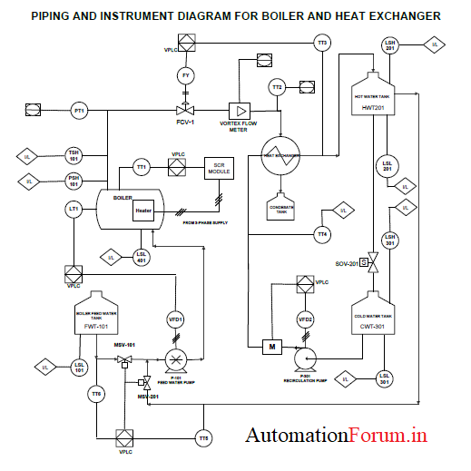
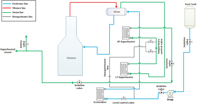
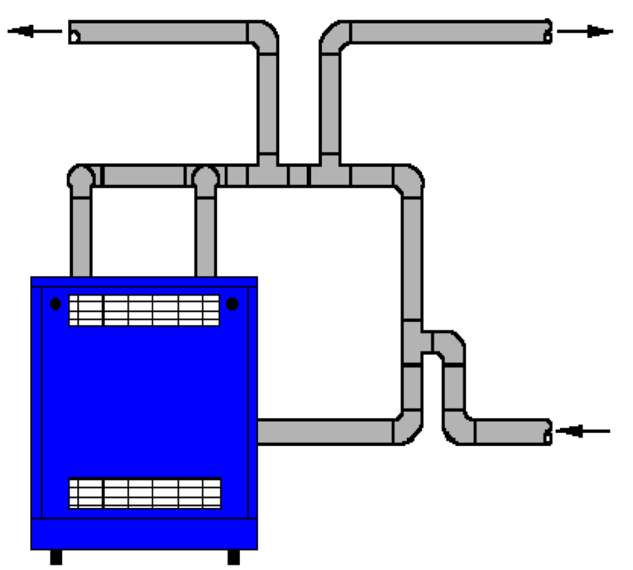
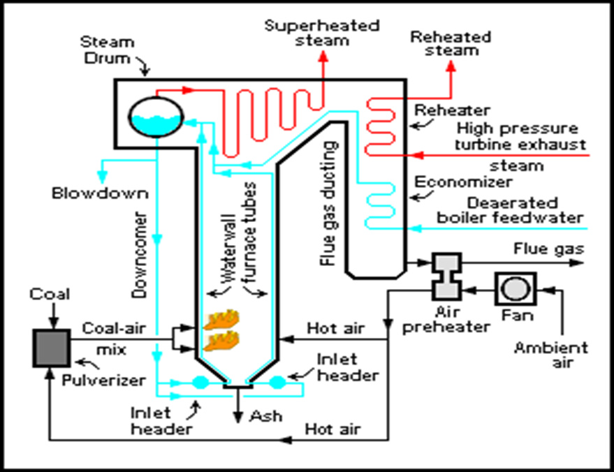
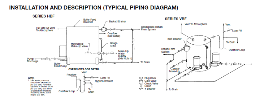
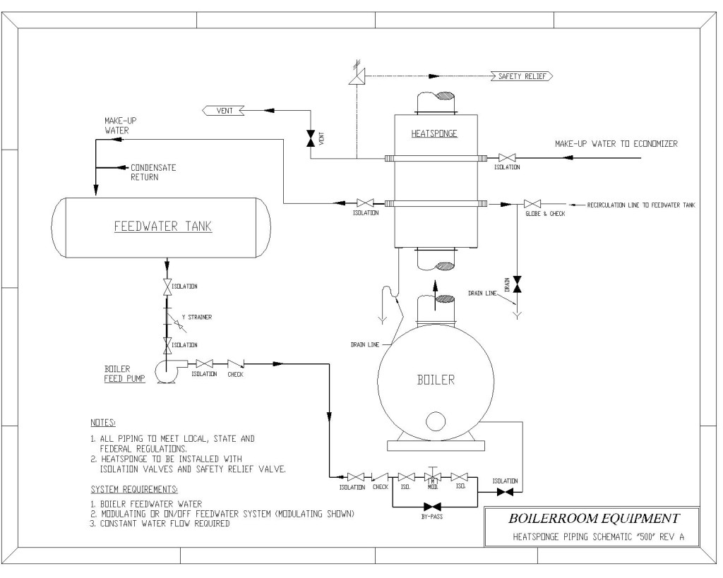
Steam boiler piping diagram
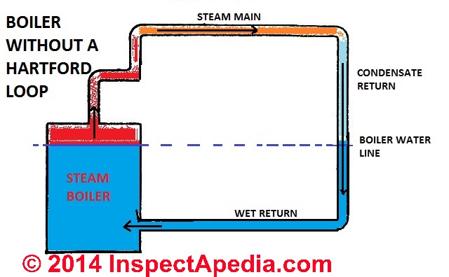
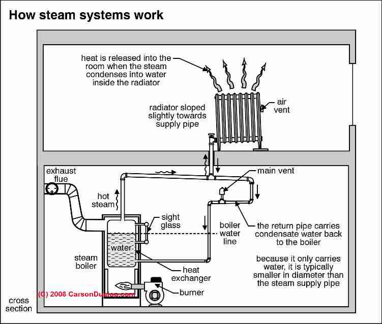
The piping must have pitch or fall to help the steam rise, and more importantly, to allow the condensate to flow back to the boiler. Level piping holds water, so it must have fallen. Also, a Hartford Loop is required to connect the supply and return.
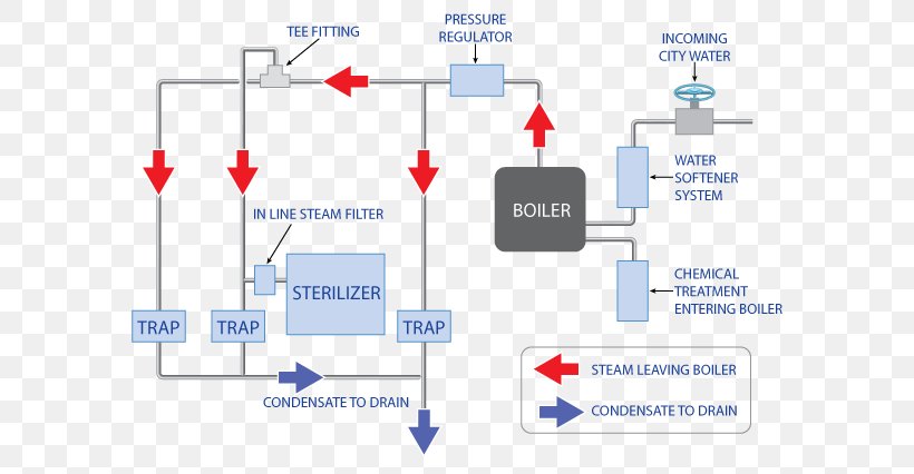
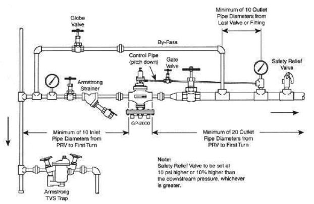
The correct way to install a PRV is shown in the above diagram. There must be a minimum distance between the PRV and sensing point, and the control line must slope down to the pipe - NOT the PRV, so that condensate will drain back to the steam line where it will be removed by a steam trap.
VENT PIPING— A. Vent piping installation must be in accordance with ANSI Z223.1-latest edition, National Fuel Gas Code, Part 7, Venting of Equipment. Other local codes may also apply and must be followed. B. Boiler vent pipe must be the full diameter of the boiler draft hood outlet. See dimensions, page 2. If a vent damper is
Steam boiler piping diagram.
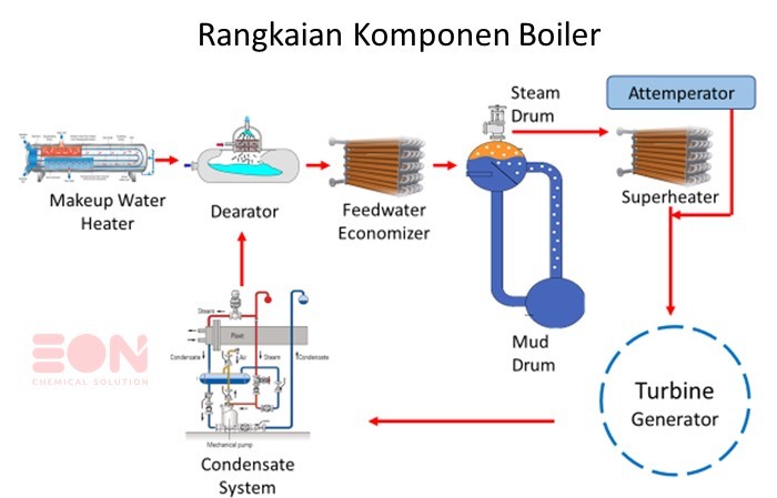
Steam Boiler Diagram With Parts for Dummy's. Below is a typical steam boiler diagram for dummy's to understand with name of each component or boiler part. First of all you should understand that there are many types and nomenclature of boilers. For example steam boiler, combi boiler, vaillant boiler, hot water boiler, gas boiler, electric ...
Equip all boilers in gravity return systems with Hartford Loop as shown in Figure 5a and 5b page 9. 7. Piping vertical risers from boiler to header, risers must be minimum of 24" high above water line.. 8. Steam riser(s) and header shall be 2" pipe size. 9. Equalizer line shall be minimum 1-1/2" pipe size. 10.
Piping Diagram - Series 64™ Near Boiler Piping Diagram - 64-09 through 64-12.
Sizing a Steam Boiler Many Steam boilers are undersized for the actual NET load Determine the BTU required for the heat load Add losses for the piping, distribution, etc. Correct for the operating pressure of the boiler Correct for the feedwater temperature of the boiler
Hot water boilers are normally used in room and process heating. This kind of system is suitable for discharge temperatures up to 140°C. The advantage of hot water over steam is that energy loss is lower than with steam boilers. 2. Thermal oil boiler In hot oil boilers is used oil in stead of steam or water. The advantage with oil is that the
System Diagrams Radiant Heat Multi Zone In-Floor 71 73 75 80 86 102 76 67 65 Forced Air vs. Radiant In-Floor Insulation Closed-cell Polystyrene Thermal Insulation OUT IN Greenhouse Heating Options Radiant PEX piping under the table Forced Air Return Supply When using mesh style tables - PEX piping must be protected from UV rays. 4 mil. black ...
Dan Holohan explains best practices for how to pipe a steam heating boiler. Learn more at www.heatinghelp.com.Want to be an expert? Read Dan Holohan's book T...
The Hartford Loop: this article gives a defnition of the Hartford Loop used on steam heating systems, explains why the Hartford Loop is necessary to protect against steam boiler damage, and gives a bit of the history of the development of the Hartford loop. We include sketches and photographs of the Hartford Loop piping arrangement on steam boilers and list inspection & defect points of interest.
Steam Boiler Piping Diagram. Sharing. Published: February 20, 2018. Categories: Steam. Steam boiler piping: The right way to pipe takeoffs from a header.
13. Wire the tank or system/pipe sensor connected to the DHW sensor terminals on the follower boiler addressed as #1. 14. The system/pipe sensor must be placed on common piping to the tank, as close to the tank as possible. 15. The system/pipe sensor is wired to the system sensor terminals on the master boiler.
piping must be the same size as the relief valve discharge opening. Avoid over-tightening as this can distort valve seats. All piping from relief valve must be independently supported with no weight carried by the valve. 1.4.5 BLOWDOWN CONNECTION Blowdown valve(s) must be full size of the connection on the boiler. Steam boilers 15 psig and
Standard Steam Boiler Plant Piping Diagram Author: Department of Veterans Affairs, Office of Construction and Facilities Management, Facilities Standards Service Subject: Standard Details Created Date: 10/7/2020 2:22:24 PM
application type diagram see installation manual for complete instructions. install in accordance with all local codes. typical piping for conventional single boiler installation lb-500, lb-750, lb-1000 • safety relief valve setting should not exceed pressure rating of any component in the system. • piping should conform to local codes.
Burnham Steam Boiler Piping Diagram Jan 7, In October, my 30+ year old steam gas boiler was replaced (had corrosion and leaking gas) with a Burnham Independence Steam boiler. It is common and acceptable practice to install these boilers in lower pressure systems, below the boiler MAWP. Therefore, Burnham offers safety relief valves set at or ...
The expansion tank must be properly. As drawn in the diagram, to charge the tank from the primary loop. 2. tanks ( where the hot water enters) and going to the Burnham boiler. ma servicing a gas steam boiler burnham piping diagram furnace ac and plumbing repair in. burnham steam boiler gas manual. steam boiler wiring diagram.
the discharge pipe between such valve and the atmosphere. Doing so can cause an accidental explosion from overpressure. The discharge from the safety relief valve shall be so arranged that there will be no danger of scalding personnel or damage to equipment. Provisions should be made to properly drain safety relief valve discharge piping.
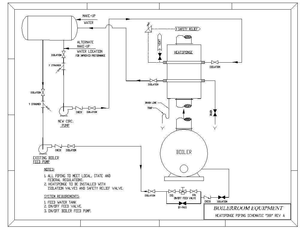
Design of Boilers and Power Piping The Boiler Manufacturer has to define where the change from Boiler to Boiler External Piping and Boiler External Piping to Non‐Boiler External Piping exists. This is typically done using Piping and Instrumentation Diagrams (P&ID's) or drawings
Product Drawings. Piping Diagram. Technical Papers. 3D-Drawings. Spec Sheets. CEMLINE® has made a series of typical piping arrangements for the Model Series: SEH, SSH, SWH, and USG. These drawings are in .DWG format or Adobe®Acrobat® (PDF) format. The Acrobat Reader is available free from Adobe. Note: Select the model and click on the ...
6.steam boiler. Steam boiler is heated with thermal water (working fluid) to produce steam equipment. It consists of boiler and furnace two parts: the pot is acceptable heat boiler and the heat to the heating surface of the working fluid system; furnace is a boiler to heat the fuel chemical energy into space and flue gas flow channel.
multiple boiler - primary/secondary piping crest . from system relief valve hot water generator water generator circulator boiler drain (typical) boiler pump (typical) ball valve (typical) air seperator drain port (typical) system circulator to system make up water back flow preventer pressure reducing valve pressure
2 Part number 550-141-829/0316 GOLD SGO OIL-FIRED NATURAL DRAFT STEAM BOILER — SERIES 3 — Boiler Manual HOMEOWNER and SERVICE TECHNICIAN — read and follow completely. The following defined terms are used throughout this manual to bring attention to the presence of hazards
The near boiler piping is the first line of defense for a reliable system. a) Correctly installed, the near boiler piping acts as a ... Steam Boiler fires. Water boils in boiler, creating steam. Surface level rises slightly because the steam bubbles displace water.
performance of a replacement steam boiler and should always be considered as part of the boiler installation. Always be sure to include clean-out and skimming tees in the near boiler piping. These "Tees" are necessary for proper cleaning and servicing of the boiler. • For further piping information refer to the I=B=R













0 Response to "44 steam boiler piping diagram"
Post a Comment