40 8145 20 wiring diagram
A wiring diagram may include the wirings of a vehicle. For example, how the horns are powered and connected to the controller on your steering wheel. Or an electrical wiring diagram can be a 200-page document including all the electrical wirings of an electrical control panel in a huge factory or... Link below has wiring diagrams and wiring manuals for 240V 8145-20 http 4001-00 is wiring diagram #1 There are 3 terminals 1 2 3 Black Hot wire from circuit breaker goes to terminal 1 Black wire to Load (light, fan, motor) goes to terminal 2 Whites wires connect to terminal 3.
Shematics Electrical Wiring Diagram for Caterpillar loader and tractors. Caterpillar 246C Shematics Electrical Wiring Diagram [PDF, ENG, 927 KB].
8145 20 wiring diagram
Mercury 75 Manual Online: 75/90 Wiring Diagram (1-2-3 Firing Order). BLK BLACK BLU BLUE BRN BROWN GRY GRAY GRN GREEN PUR PURPLE RED RED TAN TAN VIO VIOLET WHT WHITE YEL YELLOW q p o a - Stator b - Trigger c - Starter d - Starter Solenoid e - 20 Ampere Fuse f - 12 Volt... Renault Clio Wiring diagrams: Collection of multimedia schemes and wiring diagrams in several languages for electrical equipment of Renault Clio and Renault Clio Symbol 2000-2009 years of release. Renault Megane Scenic X64 NT8145 1999 Wiring Diagram.rar. Good day, ladies and gentlemen. For your consideration, I'd like to present what I believe to be the safest and mod-friendly wire diagram for a custom ESC installation, in this case 24V. I believe I have wired in two separate fail safes, both of which can be triggered by driver and one of which can be triggered remotely if desired. My wiring diagram can be used for 12V or 24V installations but for 12V you need to basically correctly choose your relays, ESC, and put the 12V LEDs in parallel so t...
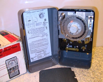
8145 20 wiring diagram. Paragon 8145 00 wiring diagram sample. A novice s overview to circuit diagrams. Yeah, reviewing a book paragon 8145 20 wiring diagram could mount up your close connections listings. Paragon 8141 00 wiring diagram free download wiring diagram wire. Wiring diagram: supplies (+ and -). components (with references, function symbols, without internal electro-mechanical details). 17 - engine electrical supply - accumulator. Exterior lighting and signalling: 20 - rear fog lamps. 8145: heated windscreen relay. 8145 20 Wiring Diagram - thank you for visiting our site. Nowadays we are excited to announce that we have found an awfully interesting niche to be pointed Some people searching for specifics of 8145 20 wiring diagram and of course one of them is you, is not it? Description : Paragon Defrost Timer... [http://www.wrxinfo.com/service\_manuals/](http://www.wrxinfo.com/service_manuals/) Been researching some torque specs for suspension stuff and was surprised about the amount of misinformation and confusion out there across forums and videos. Here ya'll go, hope this helps some of you DIYers.
Ford Wiring Diagrams - Free download as PDF File (.pdf), Text File (.txt) or view presentation slides online. All graphical aid will be bold edged. Refer to page 20 for actual example settings/layout. Wiring Harness Overview Cell 9 This section will contain a bird's eye view of the vehicle with all... I bought a spare instrument cluster for my vehicle (2008 Honda Civic) and plan on testing it with different LEDs soldered in and can't really afford the time to remove my own car's gauges every time I want to power it up so I bought [this power supply](https://www.amazon.com/dp/B08DJ1S7J5?ref=ppx_yo2_dt_b_product_details&th=1) so I could try and power it from my desk. I did hours of googling and posting on various forums to see if anyone had did a write up of which pins I needed to supp... Electric Heat Defrosting. 8145-AV. H. Models 8041-00 and 8041-20 -Wiring Diagram. Fan and compressor loads not to exceed 2 hp. Defrost timer wiring The 8045-20 is for 'Electric Heat Defrosting' Time initiated, time terminated The 8145-20 is for 'Hot Gas Defrosting' Time initiated, pressure or temperature terminatedwith back up time termination 4-110 minutes. 9045 and 9145 Universal defrost timer manual has cross-over wiring...
Electrical wiring diagrams for Audi 100 C4/4A. Format: jpg. Electrical wiring diagrams for Audi A6 C5/4B Avant Allroad. Pages: 20. Language: russian. EWD circuit diagrams of each electrical system, wiring route diagrams and diagrams showing the location of This Electrical Wiring Manual has been prepared to help inspection and service works involving electric 2019+ Acura Truck RDX AWD L4-2.0L Turbo (K20C4) System Wiring Diagrams. Hello all I'm a total newbie when it comes to this, so I wanted to run this past the community I have traced the basic backbone of my electronics, and have mapped these out in a very simplistic (I'm no engineer) layout. I've omitted fuses, and the connections for the alternator and solar panels. My question is, does the drawing make sense? Is there any fundamental issues here? I don't intend to make many changes to this setup this year, I just want to make sure I understand things properly.... WIRING DIAGRAM. Provides circuit diagrams showing the circuit connections. 2 camry (EM0250U). How to use this manual b. This manual provides information on the electrical circuits installed on vehicles by dividing them into a circuit for each system. The actual wiring of each system circuit is...
1955 chevrolet car wiring diagrams [3 MB]. 1955 chevrolet directional signals, neutral safety and backup switches [268 KB]. 1964 1966 chevrolet ck 10 20 and c30 truck fuel guage [688 KB]. 1965 chevrolet chevelle wiring diagram [545 KB].
The 8145-AV will become a mainstay in any contractor's truck. The 8145-AV reduces installation time and minimizes the number of SKUs to stock. Wiring Diagrams 8145-00 and 8145-20. Electric Heat Defrosting (SPDT Thermostat). 8000 SERIES.
-20V 4age Silvertop Wiring Diagram - Click to download Official wiring diagram for a Silvertop sourced from Toyota and translated by an unknown individual. -20V 4age wiring diagrams - Page 1, Page 2. These two pages are reported to be for the 20V Blacktop engine but have not been confirmed.
PREFACE The "Wiring Diagrams" manual documents the entire scope of series standard and additional wiring diagrams. This manual is based on wiring diagrams created using CAD. This means the manual is quick and easy to update. This manual describes the standard production...
8145 20 Wiring Diagram. June 17, 2019June 16, 2019. Sponsored links. 2005 Honda Odyssey Radio Wiring Diagram. 24 Volt Relay Wiring Diagram. Solar Panel Connection Diagram.
Wiring Diagram Elementary Diagram Form F4T Wiring Diagram Book - Schneider Electric Wiring ... 305 Pages·2008·20.79 MB·4,566 Downloads·New! Essential for electrical installers and installation designers, the IEE Wiring Regulations (BS 7671 ...
8145 20 Wiring Diagram Source: www.applianceblog.com. Before reading the schematic, get common and understand each of the symbols. Read the schematic like a roadmap. I printing the schematic in addition to highlight the signal I'm diagnosing to be able to make sure I am staying on right path.
Car Wiring Diagrams. PORTAL-DIAGNOSTOV. Login/Sign up. Wiring diagrams, location of elements, decoding fuses. Buy a subscription to access multiple vehicles. -20%.
I really need to know the pinout (numbers) for the 2010 stereo harness. I have searched for about 3 1/2 hours and come up with absolutely nothing. I have a 2008 mustang that I am putting a 2010 steering wheel on, and am wiring up the controls for volume / track via a SWC module. I need to know what pins 18 and 19 are on the 2010 mustang, and which pins those would be on the 2008 mustang. any help at all would be appreciated more than you know!
I have searched far and low and have found bare nothing when it comes to my package car. It is a SV trim level with touch-nav & no Bose premium sound package. I am trying to figure out the correct diagram in order to solder in new speaker wires to the factory wires for a amp install. I want to keep everything as factory as possible OBV. So no fancy EQ HU 🤷♂️
I’m trying to fix the panel light dimmer on my 1989 Perentie. It seems to have been disconnected by the previous owner but I don’t know what wires to connect it to, any help would be great
Wiring diagram. 30 Voltage battery, kl.30. 15 Voltage with starter key in drive position and start position, kl.15/kl.DR. 10A. XJC01_06:2. splice304_150 CU20:0 E. Relay, alternator shut down/ water heater.
TOYOTA Electrical Wiring Diagrams PDF free download - Auris, Avalon, Avensis, Camry, Corolla, Hiace, Hilux, Land Cruiser, Prius, RAV-4, Supra, Yaris. Toyota Supra Wiring Diagrams.pdf. Adobe Acrobat Document 20.9 MB.
Cooling Fans & Wiring Diagram. Смотреть позже. Поделиться.
Does anyone have a wiring diagram for the fuel pump on a 2017 6.7? After a lot of googlefication all I can find is for 7.3, 6.0, and 6.2. I’m installing a kill switch run to an upfitter switch in the cab for theft prevention.
Good day, ladies and gentlemen. For your consideration, I'd like to present what I believe to be the safest and mod-friendly wire diagram for a custom ESC installation, in this case 24V. I believe I have wired in two separate fail safes, both of which can be triggered by driver and one of which can be triggered remotely if desired. My wiring diagram can be used for 12V or 24V installations but for 12V you need to basically correctly choose your relays, ESC, and put the 12V LEDs in parallel so t...
Renault Clio Wiring diagrams: Collection of multimedia schemes and wiring diagrams in several languages for electrical equipment of Renault Clio and Renault Clio Symbol 2000-2009 years of release. Renault Megane Scenic X64 NT8145 1999 Wiring Diagram.rar.
Mercury 75 Manual Online: 75/90 Wiring Diagram (1-2-3 Firing Order). BLK BLACK BLU BLUE BRN BROWN GRY GRAY GRN GREEN PUR PURPLE RED RED TAN TAN VIO VIOLET WHT WHITE YEL YELLOW q p o a - Stator b - Trigger c - Starter d - Starter Solenoid e - 20 Ampere Fuse f - 12 Volt...


0 Response to "40 8145 20 wiring diagram"
Post a Comment