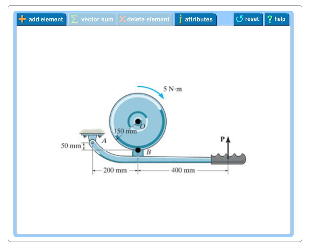
40 draw the free-body diagram for the boom. connection at a is a pin.
To set up the equilibrium conditions, we draw a free-body diagram and choose the pivot point at the upper hinge, as shown in panel (b) of (Figure). Finally, we solve the equations for the unknown force components and find the forces. Figure 12.17 (a) Geometry and (b) free-body diagram for the door. Knowing that the connection is in equilibrium and the P 400 lb and Q 520 lb, determine the magnitudes of the forces exerted on the rods A and B. SOLUTION Free-Body Diagram Resolving the forces into x and y directions: 0A BR P Q F F Substituting components: 400 lb 520 lb cos55 520 lb sin55R j i j cos55 sin55 0B A AF F Fi i j In the y-direction ...
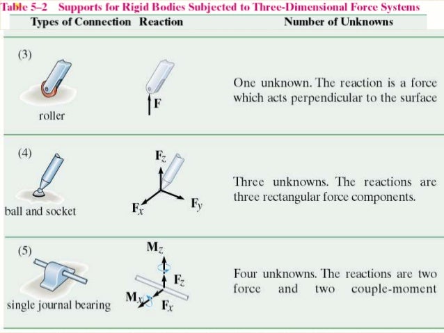
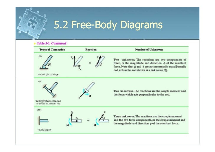
In a free-body diagram we draw the system somewhat realistically and replace ... To get a feeling for the force at a pin connection consider the physical ...
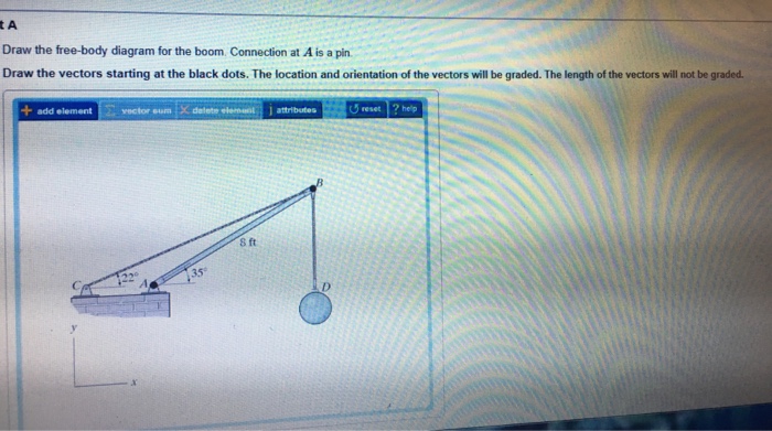
Draw the free-body diagram for the boom. connection at a is a pin.
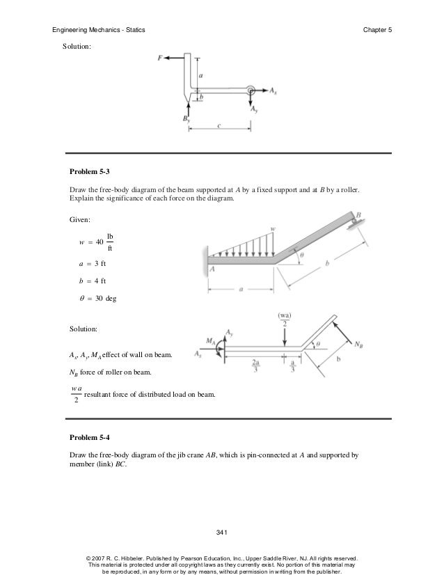
Examples of drawing free-body diagrams. To better understand how to draw free-body diagrams using the 3 steps, let's go through several examples. Example 1. A box is pushed up an incline with friction which makes an angle of 20 ° with the horizontal. Let's draw the free-body diagram of the box. The first step is to sketch what is happening: 2004-05-20 Application filed by Fox William J, Distasio Christopher C, Grodevant Scott R filed Critical Fox William J Draw the free-body diagram of the beam, which is pin- connected at A and rocker-supported at B. Page 12. 5-12. 5.3 Equations of Equilibrium. ▫ For ...
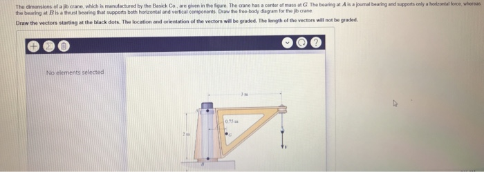
Draw the free-body diagram for the boom. connection at a is a pin.. FREE-BODY DIAGRAMS (Section 5.2) 2. Show all the external forces and couple moments. These typically include: a) applied loads, b) support reactions, and, c) the weight of the body. Idealized model Free-body diagram (FBD) 1. Draw an outlined shape. Imagine the body to be isolated or cut "free" from its constraints and draw its outlined shape. Take A Sneak Peak At The Movies Coming Out This Week (8/12) Minneapolis-St. Paul Movie Theaters: A Complete Guide; Best Romantic Christmas Movies to Watch Sec. 3.2 Free-Body Diagrams in the Equilibrium of a Rigid Body 135 Problem 3. 2-7 Draw a free-body diagram of the crane boom ABC, which has a mass of 45 kg, center of gravity at G, and supports a load of 30 Kg. The boom is pin-connected to the frame at B and connected to a vertical chain CD. Draw the free-body diagram for the boom. Connection at A is a pin. Draw the vectors starting at the black dots. The location and orientation of the vectors will be graded. The length of the vectors will not be graded. The dimensions of a jib crane, which is manufactured by the Basick Co., are given in the figure. The crane has a center of mass at G. The
5.4 Draw a free body diagram of the automobile side mirror pictured, by ... Calculate the reaction forces at the pin at point A and the roller at point B. A is a rocker and B is a pin. Draw the vectors starting at the black dots. The location and orientation of the vectors will be graded. The length of the vectors ... • A free body diagram of the complete frame is used to determine the external forces acting on the frame. • Internal forces are determined by dismembering the frame and creating free -body diagrams for each component. • Forces between connected components are equal, have the same line of action, and opposite sense. Draw the free-body diagram for the boom. Connection at A is a pin. Draw the vectors starting at the black dots. The location and orientation of the vectors will be graded. The length of the vectors will not be graded. No elements selected The dimensions of a jb crane, which is manufactured by the Basick Co, are given in the figure.
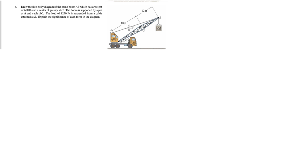
... your favorite articles to read offline, sync your reading lists across devices and customize your reading experience with the official Wikipedia app ... pin in joint B. See the diagram in the lower right of Figure 3-2. Step 2: The set of free-body diagrams is shown in Figure 3-3. Step 3: Now consider the free-body diagrams of all of the members in Figure 3-3. We have already discussed member 1, recog-nizing it as a two-force member in tension carrying forces RA and RC equal to 48.07 kN. is held in place by a pin at A and a rocker at B. The center of gravity of the crane is located at G. Determine the components of the reactions at A and B. SOLUTION: • Create a free-body diagram for the crane. • Determine B by solving the equation for the sum of the moments of all forces about A. Note there will be no Need more help! Draw the free-body diagram of the crane boom AB which has a weight of 650 lb and center of gravity at G. The boom is supported by a pin at A and cable BC. The load of 1250 lb is suspended from a cable attached at B. Explain the significance of each force acting on the diagram. (SeeFig)
Solved: Draw The Free-body Diagram For The Boom Connection ...
Free-Body Diagram: Pulley C PROBLEM 2.69 A load Q is applied to the pulley C, which can roll on the cable ACB. The pulley is held in the position shown by a second cable CAD, which passes over the pulley A and supports a load P. Knowing that P = 750 N, determine (a) the tension in cable ACB, (b) the magnitude of load Q Hence: -O: TAcB(cos250 (750
Draw The Free Body Diagram For The Truss A Is A Pin And B ...
... had a hard time dealing with China lately, caught between the draw of a billion new users and the threat of omnipresent surveillance and censorship.

Solved: Draw Necessary Free-body Diagrams For Both Problem ...
A short video to show how to form an imaginary cut and draw a free body diagram of a simply supported beam with a point load.Related videos:Reactions of a Si...

Draw a free-body diagram for the structure shown below ...
In order to continue enjoying our site, we ask that you confirm your identity as a human. Thank you very much for your cooperation
Example 1
All pieces except the pawn can capture an enemy piece if it is located on a square to which they would be able to move if the square was unoccupied.
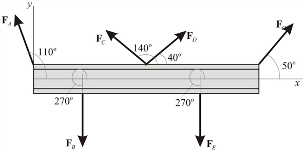
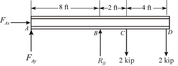
Solved: Six forces act on a beam that forms part of a ...
Free Body Diagrams. A free body diagram is a tool used to solve engineering mechanics problems. As the name suggests, the purpose of the diagram is to "free" the body from all other objects and surfaces around it so that it can be studied in isolation. We will also draw in any forces or moments acting on the body, including those forces and ...
Equilibrium & equation of equilibrium in 3D
Screen recordings of Statics Power software from Actus Potentiahttp://www.actuspotentia.com/Statics.shtml
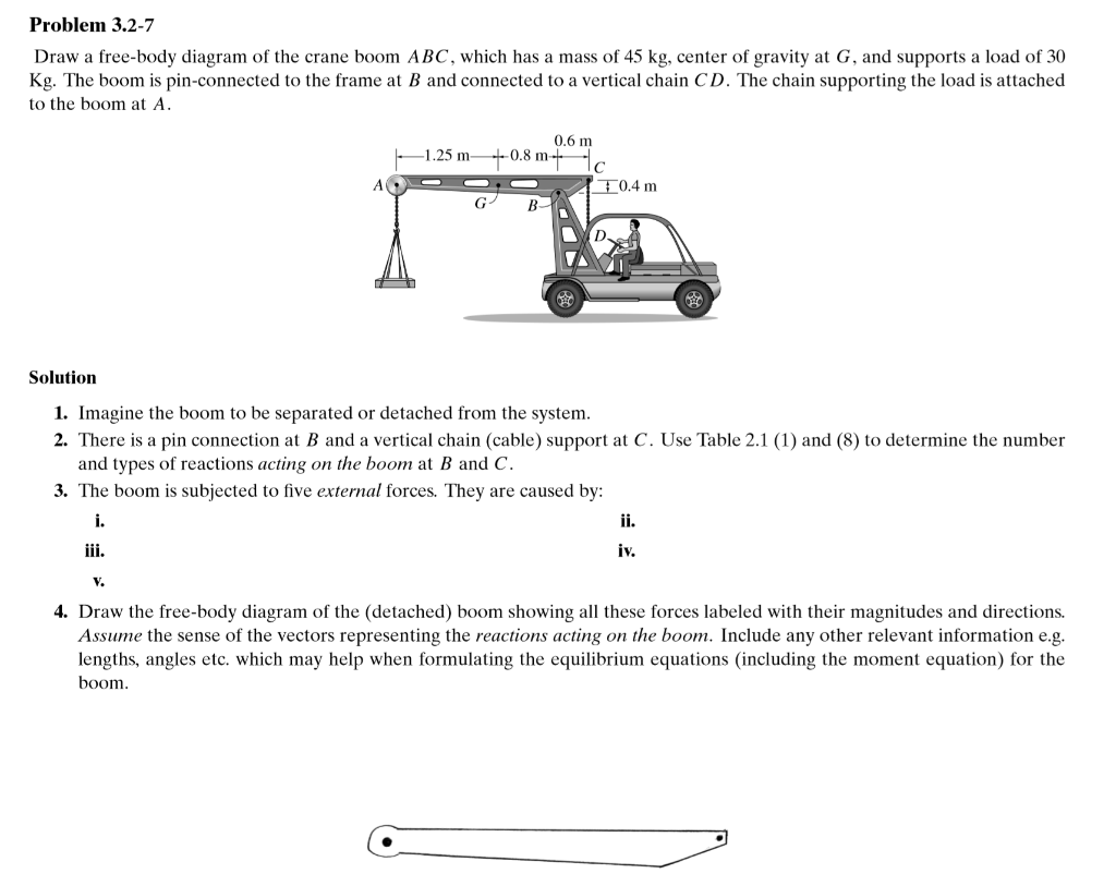
Solved: Problem 3.2-7 Draw A Free-body Diagram Of The Cran ...
We have to draw some free by diagrams for problems later in the chapter. So a problem. 32. We have a of a boom here has weight hanging from it and a cable ...
Hibbeler chapter5
Body Incomplete FBD 1. Bell crank supporting mass m with pin support at A. 2. Control lever applying torque to shaft at 0. 3. Boom 0A, of negligible mass compared with males in. Boom hinged at 0 and supported by hoisting cable at B. 4. Uniform crate of 111355 In leaning agamst smooth venicaLwall ...

How to plumb multiple shower heads -Diagram and drawing
Account Options ... Start 2022 with courses from Google , free of charge ... Advertising Programmes Business Solutions About Google Google.co.uk

30 amp rv wiring diagram - Google Search in 2020 | Diagram ...
5—6. the free-body diagram af the crane boom AB which has a weight of 650 1b and center of gravity at G. The boom is supported by a pin at A and cable BC. The load of 1250 1b is suspended from a cable attached at B. Explain Lhc significance of each force acting on the diagram. (See Dr. Ahmed A. Abu-foul T.A: Eng. Waseem (Younis 30 sithBo COS So

Draw the free-body diagram for the beam. ''A'' is a rocker ...
Figure 5.32 (a) The free-body diagram for isolated object A. (b) The free-body diagram for isolated object B. Comparing the two drawings, we see that friction acts in the opposite direction in the two figures. Because object A experiences a force that tends to pull it to the right, friction must act to the left. Because object B experiences a component of its weight that pulls it to the left ...
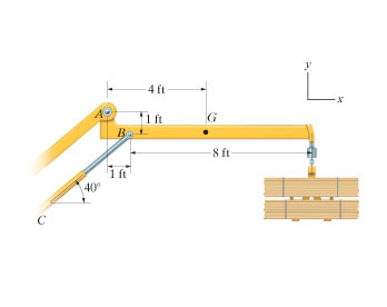
Solved: The Articulated Crane Boom Has A Weight Of 125 Lb ...
1. If the support reactions are not given, draw a FBD of the entire truss and determine all the support reactions using the equations of equilibrium. 2. Draw the free-body diagram of a joint with one or two unknowns. Assume that all unknown member forces . act in tension (pulling the pin) unless you can determine

Solved: Draw The Free-body Diagram For The Beam. A Is A Ro ...
<meta property="og:title" content="The University of Utah on Instagram: “Since Arts Bash can't be in-person this year, @uofufinearts is throwing in some added perks for tuning in to @UofUArtsPass virtually: an…”"/>
Solved: In Each Case, Calculate The Reaction At And Then D ...
13. maj 2017 ... Draw the free body diagram for the boom connection at a is a pin. My free body shows a collinear force t through the rope the given downward ...
Solved: Draw The Free-body Diagram For The Boom. Connectio ...
Free-Body Diagram.The x, y, z axes are established at B and the free-body diagram of segment AB is shown in Fig. 1-8b.The resultant force and moment components at the section are assumed to act in the positive coordinate directions and to pass through the centroid of the cross-sectional area at B. The weight of each segment of pipe is

Draw The Free Body Diagram For The Boom Connection At A Is ...
Free-Body Diagram: 2 1 2 (40 kg)(9.81 m/s ) 392.40 N (300 mm)sin (80 mm)cos (430 mm)cos (300 mm)sin (930 mm)cos Wmg a a b αα αα α == = =− =− = From free-body diagram of hand truck, Dimensions in mm MPbWaWa B 0: ( ) ( ) ( ) 0 21 (1) FPWB y 0: 2 2 0 (2) For α=°35 1 2 300sin35 80cos35 106.541 mm 430cos35 300sin35 180.162 mm 930cos35 761 ...
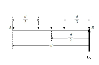
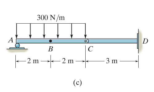
Solved: A Beam Is Subjected To A Triangular Load Distribut ...
Draw free body diagrams. Include forces ON each body being analyzed, showing point of application to indicate torques. Choose x,y, z axes. ... hanging by a rope from a boom with dimensions a = 1.9 m and b = 2.5 m. The boom consists of a hinged beam and a horizontal cable that T r T c
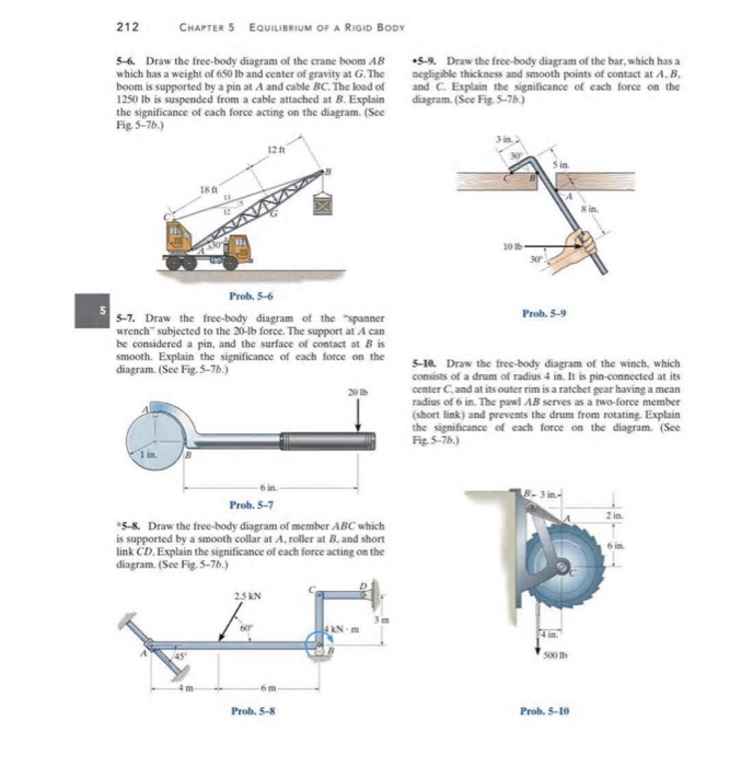
Solved: 212 CHAPTER 5 EaUILIBRIUM OF A RIGID BODY 5-6 Draw ...
Fixed or embedded connections, frictional hinges ... Add force vectors representing any loads or body forces (weights) and indicate any ... Draw FBD of Boom.
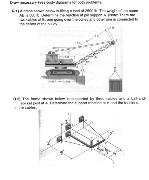
Solved: Draw Necessary Free-body Diagrams For Both Problem ...
37 Free Body Diagrams Wednesday, October 3, 2012 New Support Conditions Pin Connection ! Another way Here is a pin support 38 Free Body Diagrams Wednesday, October 3, 2012 New Support Conditions Pin Connection ! On a pin, we know that there is an x and a y component of the reaction but without other
netciateeci - moment diagram portal frame
Draw the free-body . diagrams for each pipe and . both pipes together. 5-10 Free-Body Diagrams. Solution For idealized models, Free-Body Diagram of pipe A. 5-11 p.216, 5-9. Draw the free-body diagram of the beam, which is pin- connected at A and rocker-supported at . B. 5-12
Example 1
Superimpose the distributed weight of the boom unto the load diagram showing the reaction loads of the auger, of the cylinder at the boom pin connection, and the boom pin connection to the machine structure. Of course, you have to know the vertical reactions at the auger and at the two pins connection and the distributed weight of the boom.

Draw the free-body diagram of the beam, which is pin ...
Drawing Free-Body Diagrams. Free-body diagrams are diagrams used to show the relative magnitude and direction of all forces acting upon an object in a given situation. A free-body diagram is a special example of the vector diagrams that were discussed in an earlier unit. These diagrams will be used throughout our study of physics.
Solved: Draw The Free-body Diagram Of The Crane Boom AB Wh ...
Engineering Mechanics - Statics Chapter 5 Problem 5-10 Draw the free-body diagram of the beam, which is pin-connected at A and rocker-supported at B. Given: F = 500 N M = 800 N⋅ m a = 8m b = 4m c = 5m Solution: Problem 5-11 The sphere of weight W rests between the smooth inclined planes. Determine the reaactions at the supports.

I will be glad information on the use of photos. I would be very grateful for the donation replenishment of my phone +380991680050
PROBLEM 2.F8 A transmission tower is held by three guy wires attached to a pin at A and anchored by bolts at B, C, and D. Knowing that the tension in wire AB is 630 lb, draw the free-body diagram ...

Draw The Free Body Diagram For The Boom Connection At A Is ...
16. We can now draw a free-body diagram of pin B: B 2121 N 3000 N 1500 N 1500 N 45˚ 17. Checking for static equilibrium at pin B gives: x!F = 2121 cos 45˚ - 1500 = 0 y!F = 1500 + 2121 sin 45˚ - 3000 = 0 18. We can also draw a free-body diagram for pin C: C 2121 N 1500 N 1500 N 45˚
Solved: The Block Brake Consists Of A Pin-connected Lever ...
Free-Body Diagram 4 - 4 The first step in the static equilibrium analysis of a rigid body is identification of all forces acting on the body with a free body diagram. • Select the body to be analyzed and detach it from the ground and all other bodies and/or supports. • Include the dimensions, which will be needed

Draw The Free Body Diagram For The Boom Connection At A Is ...
Pin Connection at A Ball & Socket at A. Frames and Machines Example: Free Body Diagrams Draw FBD of (a) Each member (b) Pin at B, and (c) Whole system. Example Members ACE and BCD are connected by a pin at C and by the link DE. For the loading shown, determine the force in link DE and the
Solved: Chapter 11 Problem 2RP Solution | Mechanics Of ...
Get written and oral feedback from your colleagues at the center or school for the blind and revise your course outline to incorporate their ...
Solved: A load of lumber of weight W = 25 kN is being ...
Ever since Africans were stolen from their homeland and forced to come to America as slaves, the United States has had what it used to call the ...

35 Draw The Free Body Diagram For The Beam. A Is A Rocker ...
Get the book here: https://amzn.to/2py6FInMore videos: http://www.forthesakeofeducation.comBecome my official student: ...
Support Reactions
The above diagrams, which show the complete system of applied and reactive forces acting on a body, are called free body diagrams. The whole system of applied and reactive forces acting on a body must be in a state of equilibrium. Free-body diagrams are, consequently ,often called equilibrium diagrams. Drawing equilibrium diagrams and finding
Please donate. WebMoney: Z138632687735, R330729825060, skrill- alexfoto@bigmir.net, SWIFT - KRYVYTSKYI OLEKSANDR, BIC: PBANUA2X, IBAN: UA913052990005168745600778382, I will be glad information on the use of photos.
Free-Body Diagram: First PROBLEM 4.121 The assembly shown is to collar A that fits the vertical pin shown, The pin can couples about x and t. axes but does prevent or along the For the loading shown, determine the tension in each cable and the reaction at A. 08 (0.08)2 N -e 0.6j) 12 —0.6k) T = 200N N (a) 480 N -O -480 N From D. Of assembly:

Draw The Free Body Diagram For The Boom Connection At A Is ...
Draw the free-body diagram of bar ABC. FREE BODY DIAGRAM EXAMPLE B A Draw the free-body diagram of bar ABC. Note: that the cable is in ih h FREE BODY DIAGRAM EXAMPLE tension, however the reactions at B may or may not be acting in the assumed directions. B A PROBLEM SOLVING - FBDs Draw a FBD of the bar, which has smooth points of contact at A, B ...
Draw The Free Body Diagram For The Boom Connection At A Is ...
Draw the free-body diagram for the boom. Connection at A is a pin. Draw the vectors starting at the black dots. The location and orientation of the vectors will be graded. The length of the vectors will not be graded. The dimensions of a jib crane, which is manufactured by the Basick Co., are given in the figure. The crane has a center of mass at G.

a) Draw the normal force, shear force and bending moment ...
Connection at A is a pin Draw the vectors starting at the black dots. The location and orientation of the vectors will be graded. The length of the vectors will ...

The beam is supported by a pin of diameter 18 mm at ''C ...
4.2 Free Body Diagrams The free body diagram is a depiction of an object or a body along with allthe external forces acting on it. • Choose and draw the body (with dimensions). Carefully define its boundaries. • Imagine the body in its current state and how it interacts with its surroundings. • Draw ALL the external forces acting on the ...
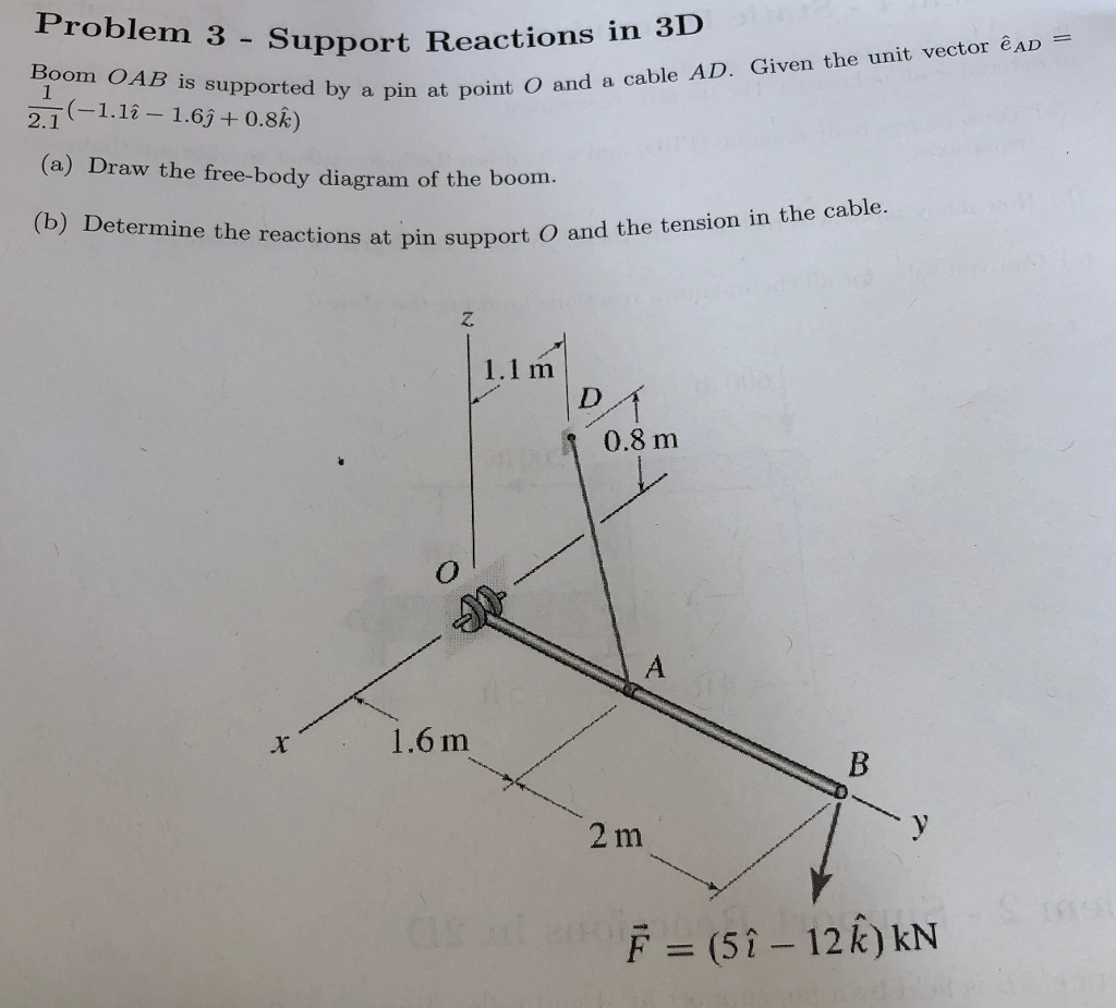
Solved: Problem 3 - Support Reactions In Boom OAB Is Suppo ...
This is one reason why I insist that teachers should always be learners, always learning something that takes them out of their comfort zone.
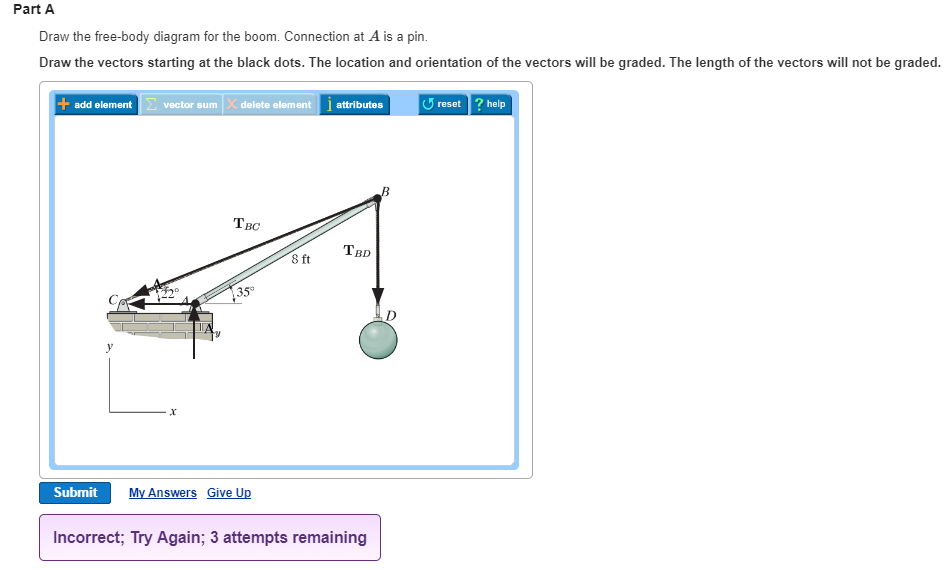
Solved: Part A Draw The Free-body Diagram For The Boom. Co ...
It applauds the fact that you were open, without particularly looking at you, and forges boldly on, being entirely stuck to the correct degree.

Patent US6263595 - Laser receiver and angle sensor mounted ...
Draw the free-body diagram of the beam, which is pin- connected at A and rocker-supported at B. Page 12. 5-12. 5.3 Equations of Equilibrium. ▫ For ...
0 Response to "40 draw the free-body diagram for the boom. connection at a is a pin."
Post a Comment