44 fe-c phase diagram
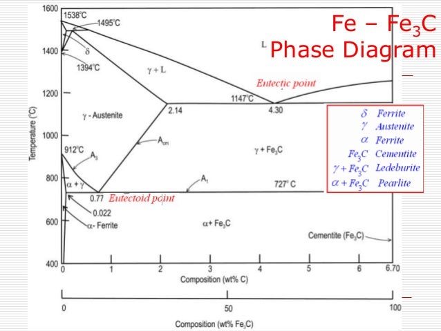
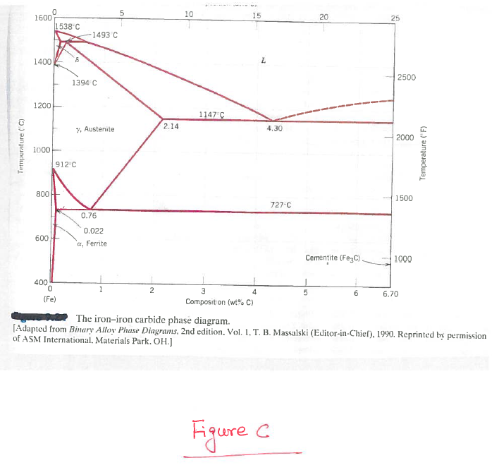
phase diagram. Concentrations C 1, C 2, C 3, C 4 are various equilibrium ( stable as well as metastable ) concentrations of carbon. c α C 1: carbon concentration in α for α-Fe 3C equilibrium. C 2: carbon concentration in α for α-γ equilibrium C 3: carbon concentration in γ for γ-Fe 3C equilibrium C 4: carbon concentration in γ for γ ... Phases Observed in Fe-C Diagram • Phases 1. Ferrite 2. Austenite 3. Cementite 4. δ-ferrite • And phase mixtures 1. Pearlite 2. Ledeburite 6. Phases Observed in Fe-C Diagram 1. Ferrite Ferrite is the interstitial solid solution of carbon in alpha iron. It has B.C.C. Structure.
Fe-C phase diagram
Fe-c phase diagram
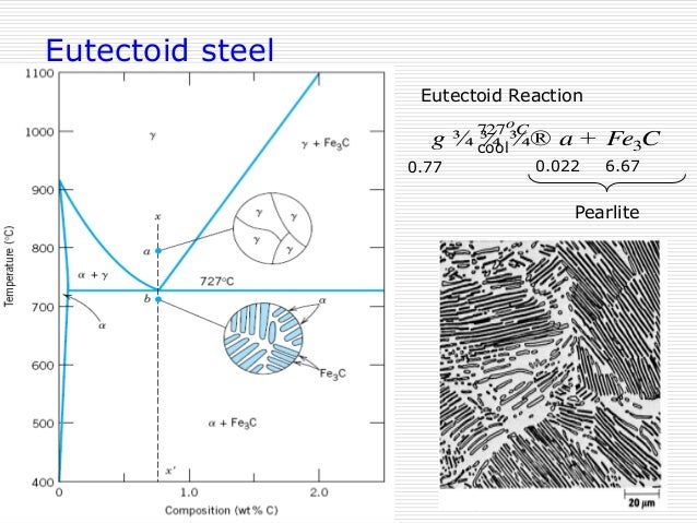
The ability to interpret this diagram is important for proper appreciation of phase changes. Fe-C diagram actually provides a valuable foundation on which to build knowledge of large variety of both plain carbon and alloy steels. Conventionally, the complete Fe-C diagram should extend from 100% Fe to 100% carbon, but it is normally studied up ... Download scientific diagram | Fe-C phase diagram (CALPHAD.com). from publication: Thermophysical properties and structure of liquid Fe-C alloys | The paper reports experimental data on density and ... transformation in relation to Fe-C diagram In order to understand the transformation processes, consider a steel of the eutectoid composition. 0.8% carbon, being slow cooled along line x-x'. At the upper temperatures, only austenite is present, with the 0.8% carbon being dissolved in solid solution within the FCC. When the steel cools through ...
Fe-c phase diagram. Review Fe-C phase diagram The influence of other alloying elements REutectoid changes. 6 Summary. 1000 700 ("t % C) ite 1000 700 500 400 72700. Fe3C 2.0 1.0 Composition (wt% C) a 0.022 C'o U Fe3C a + Fegc 6.70 Composition (wt% C) 0.76 . 0.8 0.6 0.4 0 0.2 10 12 Concentration of alloying elements (wt%) 1200 1000 800 600 2400 2200 2000 1800 In their simplest form, steels are alloys of Iron (Fe) and Carbon (C). The Fe-C phase diagram is a fairly complex one, but we will only consider the steel part ...7 pages Phases in Fe-Fe 3 C Phase Diagram ¾α‐ferrite‐solid solution of C in BCC Fe •Stable form of iron at room temperature. • Transforms to FCC g‐austenite at 912 °C ¾γ‐austenite‐solid solution of C in FCC Fe • Transforms to BCC δ‐ferrite at 1395 °C The Iron-Carbon Alloys And Fe-C Phase Diagram. The iron-carbon phase diagram and the iron-carbon systems are the most important binary systems in engineering. Steels, cast irons, and various kinds of applications are dependent on iron-carbon systems. We also explained the tin-lead phase diagram and nickel-copper phase diagrams which are also ...
A critical review of published data provides a fairly accurate knowledge of the thermodynamic properties of all of the phases of the system Fe-C that are stable or metastable at atmospheric pressure. Selected data are shown as tables and equations. A proposed phase diagram differs only slightly from others recently published but has the following features. Peritectic compositions and the α-γ ... I didn't easily find Fe-C-O phase diagram through a google search. Thermocalc says it can calculate thermo for Fe-C-O. Cite. All Answers (5) 22nd Dec, 2018. Denis Shishin. The cast iron portion of the Fe-C phase diagram covers the range between 2.08 and 6.67 wt. % C. The steel portion of the metastable Fe-C phase diagram can be subdivided into three regions: hypoeutectoid (0 < wt. % C < 0.68 wt. %), eutectoid (C = 0.68 wt. %), and hypereutectoid (0.68 < wt. % C < 2.08 wt. %). 3 phases on a Fe-C phase diagram. austenite (gamma phase), ferrite (alpha phase), and cementite (Fe3C) what are the two types of nucleation and growth. homogeneous and heterogeneous. properties of martensite. hard and brittle (rapid cooling, quenching) 3 broad categories of phase transforms.
2.2. Fe-C. The Fe-C system has been investigated in great details due to its special importance for steel. Gustafson's evaluation of the Fe-C system has been widely accepted. However, his modeling can be improved considering the following issues: (1) the liquidus of graphite in the Fe-C phase diagram is not in agreement with the experimental data , at temperature above 2400 ℃, and (2 ... The Fe-C phase diagram provides temperature-composition map of where the two phases (austenite and ferrite) occur. It also indicates where mixtures of these two phases can be expected. The Fe- C phase diagram is shown in Fig 2. In pure iron, austenite transforms to ferrite on cooling to 912 deg C. A phase diagram consists of a number of phase-boundaries separating regions of temperature- and composition-space in which different phases are stable at equilibrium. Published equilibrium diagrams for the Fe-C system often show equilibria between Fe-rich phases and both C (in the form of graphite) and cementite (Fe 3 C). Graphite is the more ... The Iron Carbon Phase Diagram. There is more to the iron-carbon phase diagram than related in the backbone. In particular, there is some nomenclature that I avoided in the main text but that is important for understanding other writings about iron and steel. So let's start with a phase diagram that contains maximal information: A 1: The upper ...
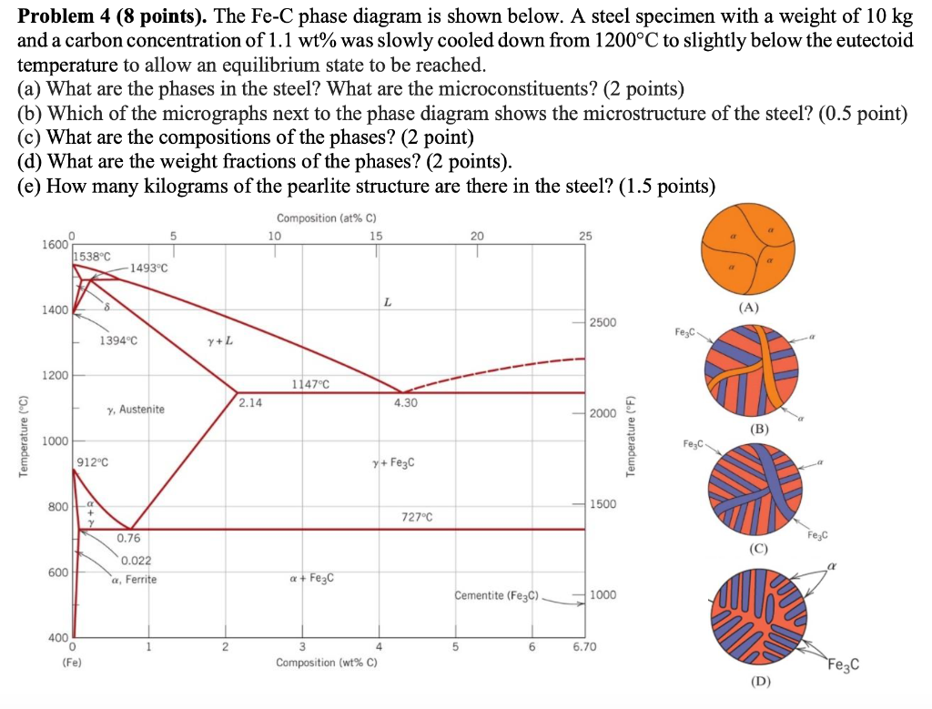
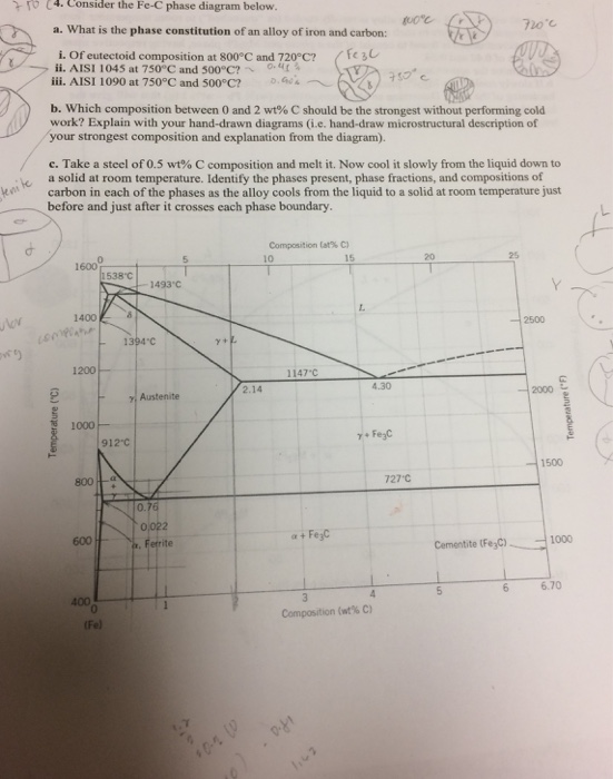
The study of the constitution and structure of iron and steels starts with the iron-carbon (Fe-C) phase diagram (Fig 1). Fe-C phase diagram is also used as the basis for the understanding of the heat treatment processes. Many of the basic features of Fe-C system influence the behaviour of even the most complex alloy iron and steels.
Fe-C Phase Diagram The Fe-C phase diagram is an important tool for the steel industry. Engineers use this diagram to design treatment techniques to produce steel that can perform in its desired applications. Notice that the composition of carbon only goes to 6.7 wt%.
C Phase Diagram. ➢ α-ferrite - solid solution of C in BCC Fe. • Stable form of iron at room temperature. • Transforms to FCC g-austenite at 912 °C.67 pages
Learn two simple ways to calculate a binary phase diagram in the Fe-C system using the graphical mode of Thermo-Calc. ~~TIMESTAMPS~~0:00 Intro0:42 How to cal...
Iron-Iron Carbide Phase Diagram | Material Engineering. The Iron-Iron carbide (Fe-Fe 3 C) is defined by five individual phases and four invariant reactions. Five phases are- α-ferrite (BCC) Fe-C solid solution, γ-austenite (FCC) Fe-C solid solution, δ -ferrite (BCC) Fe-C solid solution, Fe 3 C (iron carbide) or cementite - an inter ...
The Fe-C phase diagram is a fairly complex one, but we will only consider the steel part of the diagram, up to around 7% Carbon. A-ferrite - solid solution of C in BCC Fe Stable form of iron at room temperature. The maximum solubility of C is 0.022 wt%.
Iron-Carbon Phase Diagram with Detailed Explanation: If the percentage of the carbon is in the range of 0 to 2.11 % then it is called Steel and if the percentage of carbon is in the range of 2.11 to 6.67% then it is called Cast iron. As the carbon content increases, it produces more Iron-Carbide volume and that phase will exhibit high hardness.
The boundaries, intersecting each other, mark certain regions on the Fe3C diagram. Within each region, a different phase or two phases may exist together. At the boundary, the phase change occurs. These regions are the phase fields. They indicate the phases present for a certain composition and temperature of the alloy.
IRON-CARBON (Fe-C) PHASE DIAGRAM (EXAMPLE 1) 2 important points - Eutectoid (B) g a+Fe 3 C - Eutectic (A) L g+Fe 3 C Fe 3 e) 1600 1400 1200 1000 800 600 400 0 1 2 3 4 5 6 6.7 L g (austenite) g+L g+Fe 3 C a+Fe 3 C d (Fe)C, wt% C 1148ºC T(ºC) a727ºC = Teutectoid 4.30 Result: Pearlite = alternating layers of aand Fe 3 C phases 120 mm0.76 B g g g
Review Fe-C phase diagram • 2 important points-Eutectoid (B): γ⇒α+Fe 3C-Eutectic (A): L ⇒γ+Fe 3C Fe 3 C (cementite) 1600 1400 1200 1000 800 600 400 0 12 3 4 5 66.7 L γ (austenite) γ+L γ+Fe 3C α+Fe 3C α + γ L+Fe 3C δ (Fe) C o, wt% C 1148°C T(°C) α 727°C = Teutectoid A R S 4.30 Result: Pearlite = alternating layers of αand Fe ...
1 Assessed Fe-C phase diagram from 0 to 25 aL% Fe. Stable Fe-C (graphite) and metastable Fe-Fe3C (cementite) equilibria.
Fe-C phase diagram and microstructures ... Four different multiphase Fe-xC alloys are prepared with different ferrite and cementite amounts. X-ray diffraction ...
KEY POINTS OF Fe-C Diagram. Phases: • Liquid Fe-Tmin=1148C @ 4.3%C. • 1394 C<δ-Fe-<1538C ... When molten cast iron solidifies some of the carbon.41 pages
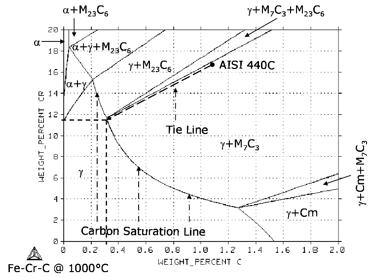
Journal of Phase Equilibria - 76Mir: D. A. Mirzaev, N.M. Mirzaeva, and Kh.M. Ibragimov, "The Fe-Cr-C Phase Diagram in the(Fe γ Cr γ)7C 3 Region,≓Sb. Nauchni.
transformation in relation to Fe-C diagram In order to understand the transformation processes, consider a steel of the eutectoid composition. 0.8% carbon, being slow cooled along line x-x'. At the upper temperatures, only austenite is present, with the 0.8% carbon being dissolved in solid solution within the FCC. When the steel cools through ...
Download scientific diagram | Fe-C phase diagram (CALPHAD.com). from publication: Thermophysical properties and structure of liquid Fe-C alloys | The paper reports experimental data on density and ...
The ability to interpret this diagram is important for proper appreciation of phase changes. Fe-C diagram actually provides a valuable foundation on which to build knowledge of large variety of both plain carbon and alloy steels. Conventionally, the complete Fe-C diagram should extend from 100% Fe to 100% carbon, but it is normally studied up ...



![Portion of Fe-C equilibrium phase diagram.[5] | Download ...](https://www.researchgate.net/profile/Tianyu_Yu3/publication/320531737/figure/download/fig5/AS:668390926585883@1536368223982/Portion-of-Fe-C-equilibrium-phase-diagram5.jpg)








0 Response to "44 fe-c phase diagram"
Post a Comment