44 hella lights wiring diagram
6" Amber Cover. 700FF (Kit) HVF Wiring Harness (2 light) Enhance your purchase. This fits your . Make sure this fits by entering your model number. Capable of simultaneously handling two lights up to 150W each at 12V. Perfect fit for Hella Value Fit LED lights and light bars. 9.5FT of wiring to allow you to mount your lights nearly anywhere you ... Harness Wiring. Note: This is a general wiring diagram for automotive applications. Use as reference only. Your lamp kit harness my have different wire colors. Locate the low beam or high beam light lead on one headlamp by using a circuit tester. Use the following procedure: For Fog Lights: Turn on the low beam headlamps. Connect the end of the circuit tester to ground (-) …
Turn Signal Flasher Wiring Diagram - led turn signal flasher wiring diagram, motorcycle turn signal flasher wiring diagram, turn signal flasher circuit diagram, Every electric arrangement consists of various unique parts. Each part should be placed and linked to other parts in specific way. If not, the structure won't work as it ought to be.

Hella lights wiring diagram
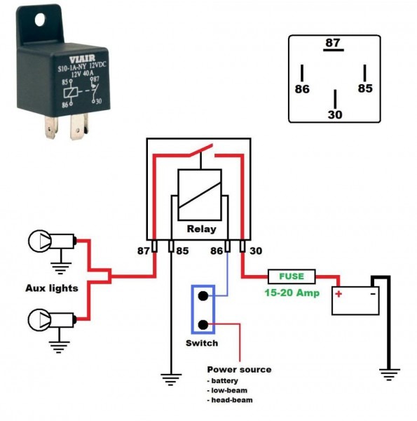
I installed my Hella 500's using the high beam activation, but there is a wiring diagram showing set up for switch activation only. I took power from the battery directly. For the switch, I just drilled out a blank switch filler plate, mounted the Hella mii rocker on the plate, and mounted it in the empty spot next to the dash light ajustment knob. The use of a Hella relay as supplied with driving and fog lamp kits, when fi tted and wired as shown in the wiring diagrams (see over), eliminates voltage loss to the lamps, ensures maximum light output and prevents overloading of the vehicle's wiring and switches. Mounting Instructions Technical. New headlamp technologies or growth areas such as thermal management and electronics create ever-changing needs as regards the necessary product knowledge and expertise for proper repair. HELLA can help you here: With practical, technical training and documentation, we will get you ready for the future. In this database, you will ...
Hella lights wiring diagram. TAV- P400 Wiring diagram TAV - P400 Manual Windows ... TAV- Carello/Hella TAV - Tools,bag, jack, shop tools ... vintage Lamborghini Lights + Hella hid lights Saco steering rack Have paddles for it Full wiring diagram for the whole car and extra computer for motor. This car is turn key ready to go runs great! 2016 tatum 1600 hp. ID# 183151 Posted Dec 26 FOR SALE $145,000 2016 Tatum Sandtruck. TATUM sand rail Two-seater Tatum sand truck Very well-maintained and cared for Very fast and dependable The best of the … The user can learn more about the wiring and lighting products from product information, animated videos, and mounting instructions. Also available on your. Features: • Wires two lamps. Wiring Harness for HELLA FF Series Halogen Lamps. H Features: • Wires one lamp • Grommet. Hella Wiring Diagram - Through the thousand pictures on-line with regards to hella wiring diagram, we all picks the very best selections together with best quality exclusively for you all, and now this pictures is actually among photographs collections in our finest ...
Single pole wire connector 8KV 705 123 813 3. Two-point mount 8HG 116 741 801 4. Switch 6EH 007 946 04 5. Hella wiring harness with relay and fuse (12V) 8KA 148 541 001 6. Bulbs: (H1 12 V / 55 W = Part no.: 8GH 002 089-131) (H1 12 V / 100 W = Part no.: 8GH 002 089-251) Accessories (not included with lamp set) Subject to alteration without notice The task of the camshaft sensor is to work with the crankshaft sensor to define the exact position of the crankshaft drive. Through the combination of both sensor signals, the engine control unit knows when the first cylinder is in the top dead point. Wiring Instructions for Auxiliary Lighting. Disconnect the battery. * NOTE: Driving lights connect to high beams, 12V+. Fog lights connect to low beams, ...2 pages Auxiliary headlights Auxiliary headlights from HELLA offer the right illumination for every application. They were especially developed to cope with the requirements of rugged situations, because people who expose themselves and their vehicles to hardship and exertion must be able to rely on their lights whatever the circumstances.
Trailer plug wiring diagram guide. Connect the earth terminal on the globe holder to the earth cable inside the lamps where tted or run. Box 89 mentone victoria 3194 hella customer service. 13 pole 7 6 west plug. Small 7 pin round qld identifying. Hella 8ja 001 918 021. This video is the complete guide to installing Hella auxilarly lights on your car. The guide is aimed at installing Hella 500, 500FF, 700, and 700FF lights,... WHERE TO BUY HELLA Products are available for purchase through a variety of sales channels, including online retailers, national retail chains, local retail stores, national mail/phone order retailers, and wholesale distributors. More Information LIGHTING Here you can find all information about products, ranges and extensions from HELLA. READ MORE > HELLA HD Here you can […] 26 Nov 2017 — ... to independently wire some Hella 500 driving lights w/ an in-cabin switch. ... but wiring diagrams read like a foreign language to me.
Hella Lights Wiring *Help* Jump to Latest Follow 1 - 7 of 7 Posts. anmut · Registered. Joined Oct 29, 2007 · 2,952 Posts . Discussion Starter · #1 · Apr 11, 2008. Only show this user ... My other question is: The wiring diagrams show a connection to the high beam from the relay. In the diagram there are three wires coming off the high beam ...
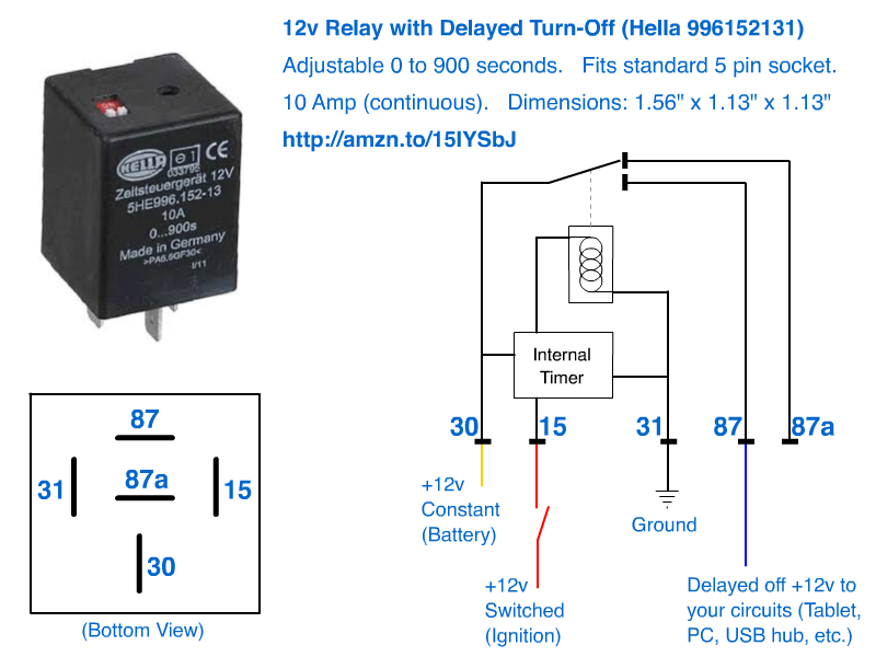
Hella Horn Relay with Wiring Harness (12V,Relay) · out of 5 stars 30 · . Received a 4RD 20A relay with no bracket. The Hella box has Wiring diagram right between the pins is perfect. Read more. OKA Relays for Automotive use - SPDT 12V 40A/30A 85 Ohm Coil. Typical Circuit. Relay Switch Circuit Diagram Hella.
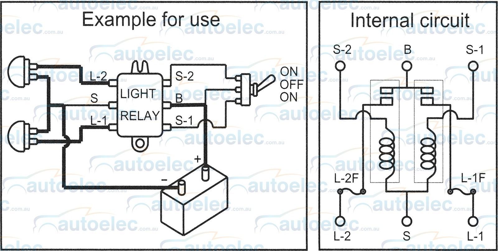
According to circuit diagram I separate switch.the auxiliary lamps are switched on together with the existing main beams. According to circuit diagram II the auxiliary lamps can be switched on in addition to the main beams with a Lay and connect wires according to circuit diagram.
Use a multi/ohm meter to see whether there is continuity with either lead to the base, but Hella usually uses yellow as 12V+ and blue as a switched 12V- (Ground). 3-wire Typical Hella suggests that yellow is the 12V+ for the main beam, brown is 12V- (Ground) and blue is the 12v+ for the parking lamp.
If I needed more, which I don't, I'd buy Hella again! The drawback was the wiring kit and switch that it came with. Definitely not capable of running four lights on one kit of wires. The instructions were pretty much jargon, the switch wasn't that appealing. Understandable though, the wiring kit can work, as long as you can figure out the diagram they provide! ...
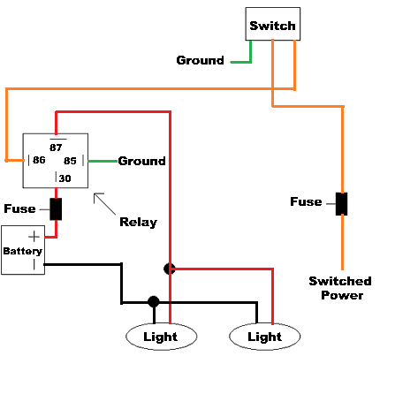
diagram of wiring procedure. Note: The Hella Wiring Harness supplied with this kit is a complete assembly. It is fully insulated and sleeved. All connections are pre-terminated. 3. Mount Relay as follows: (See A in Fig. 4) a. Position the relay upright on the battery side of the engine compartment in an area that is not exposed to water spray ...

Unlike the traditional routes it takes to achieve beautiful scenery involving long strenuous hikes or long walks through winding forests. Hong Kong is a complex maze that awards those who find the right spots and correct elevators that take you right up to view this beautiful puzzle in all its glory.
If I needed more, which I don't, I'd buy Hella again! The drawback was the wiring kit and switch that it came with. Definitely not capable of running four lights on one kit of wires. The instructions were pretty much jargon, the switch wasn't that appealing. Understandable though, the wiring kit can work, as long as you can figure out the diagram they provide! ...
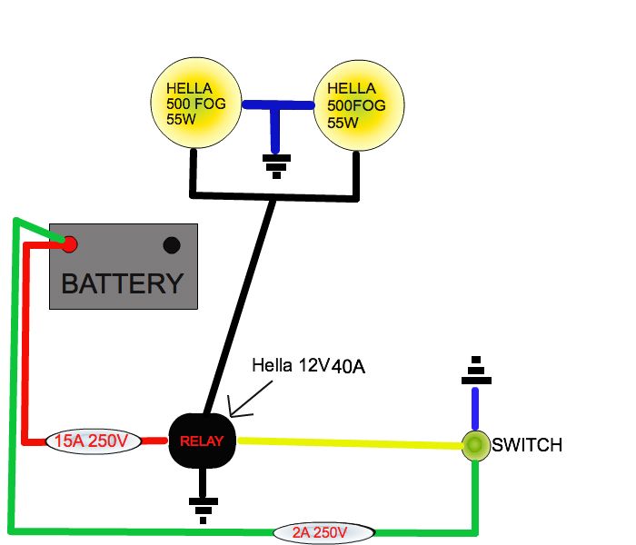
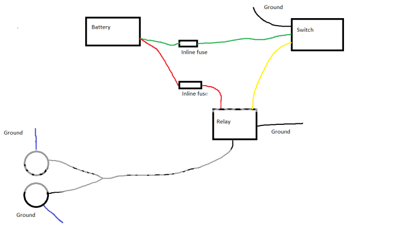
Hella Ultimate Style/Black Magic Driving Lamp System. INSTALLATION (1) Complete wiring system with 12V/30A relay, in- 4 for diagram of wiring.This wiring diagram will stay with the car so make it neat and easily readable. Pictured is my wiring diagram for installing two fog lights with fuses, a switch, and a relay.
Driving lights and fog lights came about as car owners navigated the Pictured is my wiring diagram for installing two fog lights with fuses. The use of a Hella relay as supplied with driving and fog lamp kits, when fitted and wired as shown in the wiring diagrams (see over), eliminates voltage loss to .
Choose items to buy together. This item: HELLA 148541001 Rallye 4000 Wiring Harness. $91.01. Only 18 left in stock (more on the way). Ships from and sold by Amazon.com. FREE Shipping. HELLA H12560021 Rallye 4000 Series 12V/100W Halogen Euro Beam Lamp - Black Housing , White. $110.61.
4 Dec 2007 — :thumbsup: !! one question though, my relay has two posts stamped 87, which is power out to lights. does that mean i need to have one coming off ...
2021-12-13 Digital FlatLight from HELLA enables customizable light signatures and communication more 2021-11-29 HELLA publishes preliminary key figures for the second quarter of the fiscal year and adjusts company outlook for the current fiscal year due to expected lack of market recovery in the second half of the year and increasing cost ...
18 Sept 2016 — I got these Hella 500 fog lamps to mount on the front of my 60. ... all the time. here are a couple diagrams to help out with wiring the ...
Relays Wiring Diagram Atv Wiring Connectors Tempuyak Square4 Ponechik It . Complete Wiring Harness Loom Assembly With Fuse Box Farmtrac 45 Tractors Fuse Box Tractors Fuses . Defender 90 2 8i Spotlights Motorcycle Wiring Automotive Electrical . Hella 500 Fog Light Wiring Diagram Beacon Light Wiring Diagram For Wiring Diagram Schematics
Hella wiring diagram doesn't help. Is a 25 Amp fuse sufficient I have one pencil and one spread - should the spread beam be on the ... Spot beam is usually mounted on the drivers side. Were dose this yellow wire go to in the light that should tell you what it is for, and yes 25 amp should be fine as I= w/v so 200 watts divided by 12 volts = 16 ...
The use of a Hella relay as supplied with driving light kits, when fitted and wired as shown in the wiring diagram, eliminates voltage loss to the lights and ensures maximum light output and prevents overloading of the vehicle's wiring and switches. For lamps not supplied with relay Fused Unfused Recommended Hella 3076 12 volt 3078 12 volt
25.12.2016 · DIY: Wiring after-market lights - Tacoma World Forums DIY: OEM Cruise Control - Toyota Forums :: Toyota Nation OEM Intermitted Wipers DIY - Toyota Forums :: Toyota Nation 2005 Tacoma-Writeup on door panel removal - CustomTacos.com Forum Installing AAL's by Chris4x4 Wire Diagram for Anytime Foglight mod by Crom Bed rail attachment hardware
Fog light wiring diagram with relay. Failure to do so would cause excessive heat in the wiring and switch and create a risk of fire. Pictured is my wiring diagram for installing two fog lights with fuses a switch and a relay. It is for this reason that we present here the proper way to wire a fog light systems.
This is how I wired up my Hella 500's. When you get these lights, I would highly recommend just tossing the wiring harness that comes with it and making your own with quality parts. Especially the in-line fuse holders. This is my first write up.
Mounting instructions. Hella Rallye Compact Series 4 RA 6 . Hella wiring harness Choose the circuit diagram (I -. IV) applicable for you. We're installing a set of Hella Rallye headlights that are perfect off Next, the wires to power the bulb are attached and the reflector is 4. I am trying to wire up Hella Rallye Halogen lights, (a pair of ...
17.04.2015 · A wiring diagram from your shop manual lists the number of grounding points and their locations. If they are missing or no longer functional, correct replacements are available. Once the grounds have been attended to, it is time to move on to the other connections in the car. A multi-tester is a very handy and useful item for tracking down shorts and bad connections. …
Australia uses basically the same wiring with the exception for pin 5 and pin 2. The problematic part here is that pin 5 is used for trailer brake which means that if you for some reason connect an Australian trailer to a towing vehicle with ISO wiring you will get into trouble with the trailer brakes being applied as soon as you turn on the lights.
Hella Hid Ballast Light Wiring Diagram I have a used hella ballast off a 02 Mercedes ML with Bi-xenon and the If I want test this ballast did anyone know the wiring diagram?. Connect the bulbs to the ballast harness making sure the safety clips on the connectors are fully Fitting a HID kit internally to a Hella Rallye driving light.
16 Jun 2017 — So I was looking at the wiring diagram for these driving lamps I'm installing:
Susquehanna MotorSports 458 Main St. Virginville, PA 19564, USA Call Us: 610 944 3233 FAX: 610 944 3234
familiarize yourself with the contents of your Hella FF Series Lamp System. Contents: (2) Hella FF Series Lamps. (1) Wiring harness. • Electric drill.3 pages
24.03.2021 · The harness uses heavy duty 12 gauge wiring and Bosch-Tyco TE European relays with ceramic plugs to bypass the factory wiring and switches, drawing power directly from the battery. The 12 gauge heavy duty wiring with a direct lead to the battery is more efficient, reducing voltage drop and causing your lights to burn brighter, and isolates the factory wiring …
Technical. New headlamp technologies or growth areas such as thermal management and electronics create ever-changing needs as regards the necessary product knowledge and expertise for proper repair. HELLA can help you here: With practical, technical training and documentation, we will get you ready for the future. In this database, you will ...
The use of a Hella relay as supplied with driving and fog lamp kits, when fi tted and wired as shown in the wiring diagrams (see over), eliminates voltage loss to the lamps, ensures maximum light output and prevents overloading of the vehicle's wiring and switches. Mounting Instructions
I installed my Hella 500's using the high beam activation, but there is a wiring diagram showing set up for switch activation only. I took power from the battery directly. For the switch, I just drilled out a blank switch filler plate, mounted the Hella mii rocker on the plate, and mounted it in the empty spot next to the dash light ajustment knob.












![The Road to Hell[a] part two...](https://images.unsplash.com/photo-1613379293095-d81837c1502d?ixlib=rb-1.2.1)
0 Response to "44 hella lights wiring diagram"
Post a Comment