45 autometer fuel level gauge wiring diagram
Irvan-Smith, Inc. : Do-It-Yourself Kits :Start from scratch, design and build your you very own pit carts, pit wagon or tire rack with our Do-It-Yourself Kits. Kits allow you to determine the size of the cart and incorporate any toolbox that you may already have readily available. We also offer Bottom Frames giving you a starting point and you build it from the frame up. Also ... wiring instructions. Always disconnect battery ground before making any electrical connections. Parts of the Fuel Level Sender Unit to be Ad Fuel Level Sender Installation: Refer to the VDO catalog for matching fuel gauges. The unit can be adjusted to read accurately in tanks from 6" to 23" deep. Diagram B I. Measure the depth of your fuel tank.
the reason is that the autometer gauge, an american product, is designed to compensate for "dumb" fuel sending units. our sender, a japanese product, already does this compensation, sending a nearly perfectly linear signal, very much indicative of the actual fuel level. our oem gauge is "dumb" in that the needle's indication is directly ...
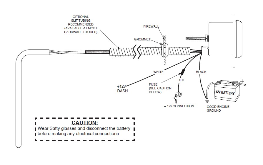
Autometer fuel level gauge wiring diagram
Use 20 AWG.Sep 19, · Updating To An Electrical Gauge Package Hotrod Hotlinerhhotrodhotline also Auto Meter Speedometer Wiring Diagram Schematic Electronic Rhselfitco further Auto Meter Tach Wiring Diagram On Hei Trusted Diagramsrhkroudco in addition Autometer Fuel Level Gauge Wiring Diagram Electrical Diagramsrhwiringforalltoday and Wiring ... Aug 11, 2017 · Gm Tbi Tps Wiring Library Of Wiring Diagram Within Throttle Chevrolet Throttle Position Sensor Diagnosis And Repair Help 1996 1998 Throttle Position Sensor Circuit ... Isspro pyrometer gauge wiring the hull truth boating and fishing forum weird electrical issues turbo sel register installation instructions for optional a relay controlled output caution autometer c2 pyro place tech egt exhaust gas temperature westach westberg diagram digital boost vac 2650 1236 00 manualzz work hours counter android 2 1 16 0 1600 f stepper motor sport… Read More »
Autometer fuel level gauge wiring diagram. Autometer Fuel Level Gauge Wiring Diagram - wiring diagram is a simplified all right pictorial representation of an electrical circuit. It shows the components of the circuit as simplified shapes, and the capability and signal friends between the devices. A wiring diagram usually gives guidance practically the relative incline and treaty of ... 6.5 turbo diesel injection pump turn up. May 29, 2021 · Answer: FYI - There are lots of YouTube videos on this… Also, we are assuming you have done all the diagnostic work to confirm that the pump is actually bad. 5 td. p1214 --- 88 injection pump timing offset p1216 --- 35 fuel solenoid response time too short p1217 --- 36 fuel solenoid response time too long p1218 --- 56 injection pump ... Latest information about coronavirus (COVID-19), online services and MyAccount, customer services and how to make a complaint. Step 4. Connect the "S" wire to the fuel-sender signal wire you removed from the stock fuel gauge. This wire is fed directly to the post on the fuel-level sender in the fuel tank. Twist these two wires together and cover them with a layer of electrical tape. Use your test lamp to determine the fuse for the dashboard instrument lights.
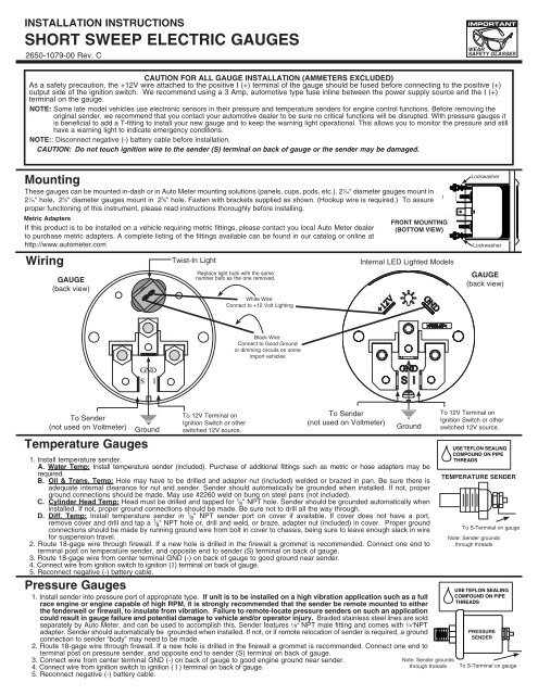
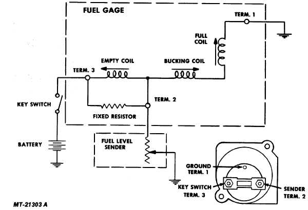
I just got done installing a new fuel level sending unit in my 86 gt mustang and purchased a new autometer fuel gauge to go with it. But as far as wiring is concerned, I don't have a clue. Someone had mentioned that I could t-tap a wire off of the stereo power wire (which I did). But I can't seem to get the damn thing to work. ( 56004879 ) Replacement Fuel Level Gauge for 1992-1995 Jeep Wrangler YJ Model Years by Omix-Ada. $36.95. ( 56004880 ) Replacement Oil Pressure Gauge For 1992 ... Chrysler wiring diagrams are designed to provide information regarding the vehicles wiring content. Fuel level. 1. Gauge connects to fuel sender on fuel tank. GAUGE (back view) Wiring Ground Note: Sender grounds through threads Black Wire: Connect to Good Ground or dimming circuits on some import vehicles GND S I Pressure Gauges Temperature Gauges TEMPERATURE SENDER USE TEFLON SEALING COMPOUND ON PIPE 1. Install temperature sender. Fuel gauge troubleshooting begins with isolating the problem either to the gauge, sending unit, fuse or wiring. The most common gauge problems are either a bad ground at the tank, or a sender problem. As with any electrical troubleshooting, it is best to check the fuse and all wiring connections are clean, tight and free of corrosion.
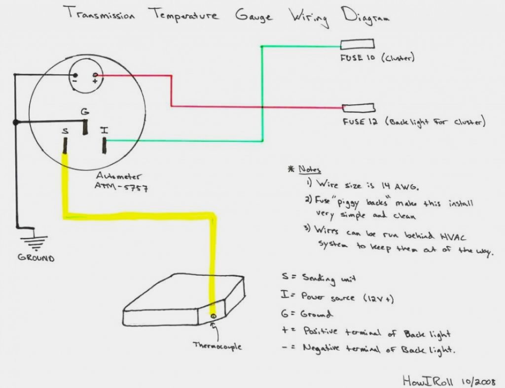
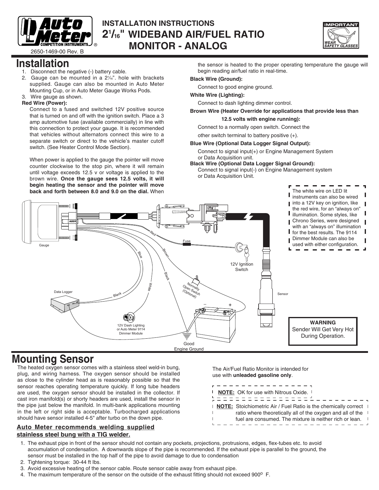
Trans Temp Gauge Installation: but an A-pillar gauge mount is available as a professional location to mount two gauges. diagramweb.net has a 2 & 3 gauge pod available Pictured below is a copy of the wiring diagram for the Autometer Transmission Temperature Gauge. STEP 4. Auto Meter Replacement Harness For Full Sweep Electric Pressure Gauges. Autometer gauges faulty after wiring fuel ratio monitor installation auto meter 3810 user manual 2 pages how to install oil pressure 3363 sensor 1 16 0 100 psi air gauge wrangler tj on your jeep cobalt wideband wire harness for elite start kart plans troubleshooting boat 5 ultra replacement full 5763 electric 2198 ... Those autometer gauges never work just right even if you get them adjusted right. Vince and doc and cletis are all right, the sender needs to be matched to the gauge. There are about 5 or more ranges that those run in, 90-0 ohms, 0-90, 240-33, 73-10,10-180 all different resistance values for different gauge mfgs. Equus tachometer wiring diagram further how install tach also r1 tach wiring diagram moreover rpm circuit diagrams further autometer fuel level gauge wiring diagram as well as autometer fuel gauge wiring diagram as well as honda shadow wiring diagram as well as honda bf50a tachometer wiring diagram furthermore autometer volt install along with ...
5. Connect the other end of the wire to the Speedometer. Fuel Level Gauge 1. Attach the ground ring connector and positive wire using a ring connector to the gauge. 2. Pick a color wire for the sending unit wire and connect it to the gauge using a ring connector. 3.
Wiring diagram for auto meter new wiring diagram auto gauge a newbie s overview of circuit diagrams. Toll free tech support. Pin On Gauges . Higginbotham fuel gauge wiring diagram rate fuel gauge wiring autometer gauge wiring diagram additionally wiring diagram provides you with enough time frame by which the assignments are to be accomplished.
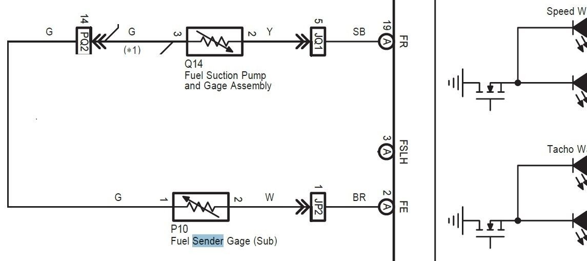
A port injection system which consisted of a fuel suction tube with pump and gauge assembly, fuel pipe sub-assembly and fuel injector assembly. Based on inputs from sensors, the ECM controlled the injection volume and timing of each type of fuel injector, according to engine load and engine speed, to optimise the fuel:air mixture for engine ...
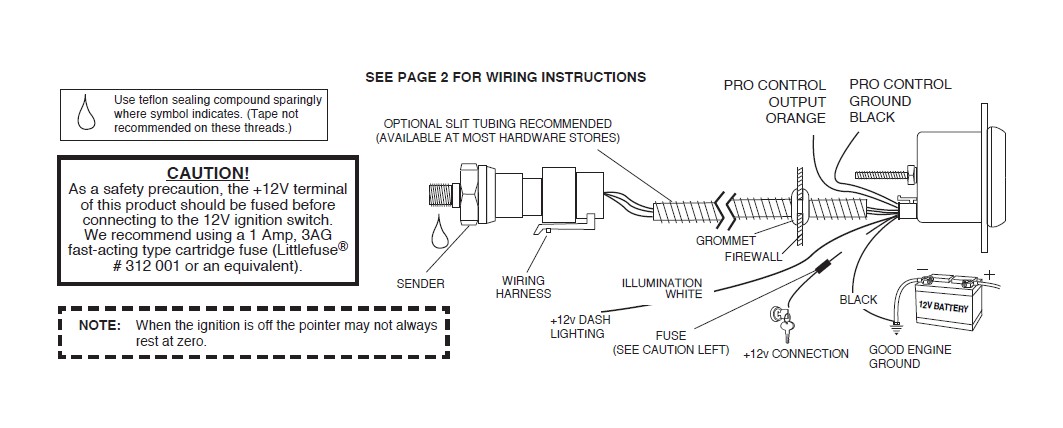
4. Connect the purple sender wire to the fuel level sender. Existing wires may be used, or route the purple sender wire to the fuel tank. (The stock fuel level gauge, if equipped, must be disconnected.) 5. Connect the white wire to dash lighting or switchable 12v light source. 6. Connect one of the black wires to a good ground.
Jul 11, 2019 · boat 12v switch panel wiring diagram; boat fuel sending unit wiring diagram; boat stereo wiring diagram; boat switch panel wiring diagram; boat trailer wiring diagram 4 wire; boat voltage gauge wiring diagram; bobcat skid steer wiring diagram; bosch relay headlight wiring diagram; bosch universal oxygen sensor wiring diagram; boss snow plow ...
Autometer Phantom Fuel Gauge Wiring Diagram. By Admin | November 2, 2017. 0 Comment. Auto meter 4379 user manual 2 pages also for 8079 1 16 fuel pressure 0 100 psi stepper motor phantom air ratio gauge 5737 electric water temperature gauges interior accessories cajaalimentos com br 21 wide band monitor 3810 5910 8010 1109 narrowband lean rich ...
The AutoMeter Digital Stepper Motor Fuel Level Gauge drastically simplifies the process with its easily configurable resistance range. With 7 common configurations stored in memory from the factory, the vast majority of all applications are covered. In the instance your fuel level sender is not included in these preconfigured ranges, an ...
I installed this unit into a 2001 F250 (Ford truck) and the Aerpro fitting kit and wiring harness make life extremely easy for the installation and the finish is excellent. The digital radio options make it easy to locate stations but be prepared to have drop-outs of signal if you live in fringe areas.
A wiring diagram is a simplified conventional photographic depiction of an electric circuit. Existing wires may be used or route the purple sender wire to the fuel tank. The stock fuel level gauge if equipped must be disconnected 5. Connect ground wire from ground post on gauge to suitable chassis ground. Gauge mounts in a 25 8 hole for 2 5 8 ...
I have a autometer 7114 autometer c2 programmable fuel level gauge purple goes to sending unit wire but i don't have wiring diagram for a 1997 f150 4.2 v6 i have 4 wires 1 large pink/blue, 1large black, 1yellow small,1 small black/orange, from factory unit ,purple to which one? i don't want pull gas tank.
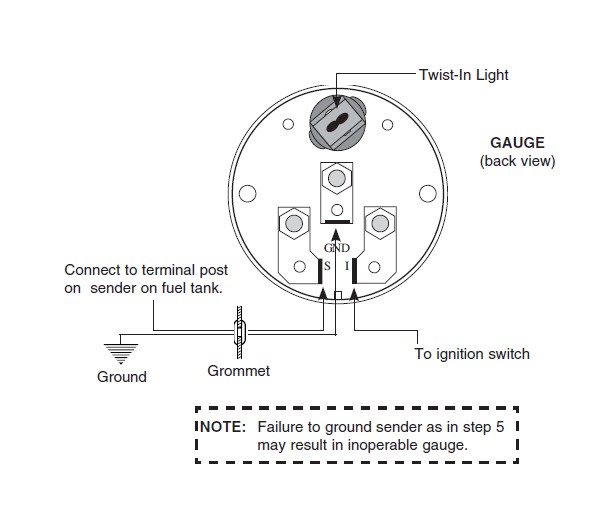
Fuel Level. 1. Gauge connects to fuel sender on fuel tank. Existing wires may be used, or route proper length of 18 gage, wire from fuel tank to gauge. If a new hole is drilled in the firewall a grommet is recommended. Connect one end to terminal post on fuel level sender and the opposite end to the sender (S) terminal spade on back of gauge. 2.
Autometer Gas Gauge Wiring Diagram. Auto meter 3810 user manual 2 pages also for 5910 8010 1109 installation instructions cobalt air fuel ratio gauge digital 79 17 all americanmuscle spridgetguru com tech index wiring diagram how to test and replace your sending unit sail magazine 21 16 quot monitor install direct fit dash panel 97 06 wrangler ...
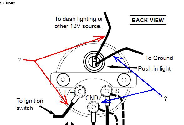
2. Using 18-ga. wire, connect the (G) terminal to a clean (rust/paint-free) Figure 4ground. 3. Using 18 gauge wire, connect the (I) terminal to a switched +12V source. 4. Using 18-gauge wire, connect the (S) sender terminal of the gauge to the fuel level sender. 5. Connect one the light wire to the dash lighting circuit or to a +12V switched ...
Nov 04, 2018 · automatic transmission schematic diagram; autometer autogage tach wiring diagram; autometer tach wiring diagram; autometer volt gauge wiring diagram; aux to usb cable wiring diagram; avr vr6 wiring diagram; avs 7 switch box wiring diagram; avs switch box wiring diagram; badland winch remote control wiring diagram; badland wireless winch remote ...
Fuel Level 1. Gauge connects to fuel sender on fuel tank. Existing wires may be used, or route proper length of 18 gage, wire from fuel tank to gauge. If a new hole is drilled in the firewall a grommet is recommended. Connect one end to terminal post on fuel level sender and the opposite end to the sender (S) terminal spade on back of gauge. 2.
Feb 08, 2018 · Plug and Play with AutoMeter Electronic Programmable Speedometers. Lightning quick 10 Hz signal update rate is the fastest available. Fully sealed and paintable magnetic micro antenna (Dimensions: 1.472 in. x 1.339 in. x 0.508 in.). Includes 16 ft. of wiring for plenty of mounting versatility. GPS module is fully sealed against water and dust.
SHORT SWEEP ELECTRIC FUEL LEVEL GAUGE 2650-1858-77 Wiring: Sending Unit Wiring: Gauge Mounting: Gauge to Sender Compatibility: Looking at the rear of the gauge, you will have 3 terminals labeled S, I, & GND. You may use 18g or 20g stranded wire for all fuel level gauge wiring. S = This connects to the sending unit in the fuel tank. **(See ...
Auto Meter Products. 413 W Elm St. Sycamore, IL 60178. Toll Free Tech Support: 866.248.6357. Toll Free Customer Service: 866.248.6356. International: 815.895.8141
17 Universal Motorcycle Speedometer Wiring Diagram Motorcycle Diagram Wiringg Net In 2020 Odometer Types Of Electrical Wiring Digital . Pin On Gauges . Pin On Gauges Car And Truck Parts . Pin On Gauges . Sponsored Ebay Autometer 201011 Cobra Electric Fuel Level Gauge Gauges Electricity Fuel Pressure Gauge
Fuel Level Gauges Autometer How They Work How To Install Tutorial Instructions Ohms Wiringhttp://www.jegs.com/vct/Auto+Meter/105/1010331-----...
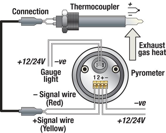
Isspro pyrometer gauge wiring the hull truth boating and fishing forum weird electrical issues turbo sel register installation instructions for optional a relay controlled output caution autometer c2 pyro place tech egt exhaust gas temperature westach westberg diagram digital boost vac 2650 1236 00 manualzz work hours counter android 2 1 16 0 1600 f stepper motor sport… Read More »
Aug 11, 2017 · Gm Tbi Tps Wiring Library Of Wiring Diagram Within Throttle Chevrolet Throttle Position Sensor Diagnosis And Repair Help 1996 1998 Throttle Position Sensor Circuit ...
Use 20 AWG.Sep 19, · Updating To An Electrical Gauge Package Hotrod Hotlinerhhotrodhotline also Auto Meter Speedometer Wiring Diagram Schematic Electronic Rhselfitco further Auto Meter Tach Wiring Diagram On Hei Trusted Diagramsrhkroudco in addition Autometer Fuel Level Gauge Wiring Diagram Electrical Diagramsrhwiringforalltoday and Wiring ...


![DOWNLOAD [DIAGRAM] Waste Oil Wiring Diagram Full Quality ...](https://rennlist.com/forums/attachments/944-turbo-and-turbo-s-forum/75591d1125497264-oil-temp-gauge-sender-wiring-vdo-gauge-install.jpg)



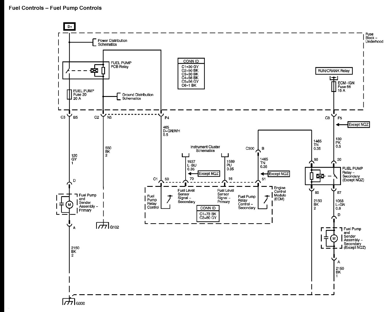


![!/[PDF] Gm Fuel Sending Unit Wiring Diagram](https://i.pinimg.com/originals/98/3d/7a/983d7a09f3be0ed82972dffc00ae7459.png)









![[SG_3032] Wiring Autometer Volt Gauge Free Diagram](https://static-cdn.imageservice.cloud/915175/autometer-speedometer-wiring-quick-view-dakotanauticacom.jpg)
0 Response to "45 autometer fuel level gauge wiring diagram"
Post a Comment