45 free body diagram beam
Figure M4.3-7 Geometry and free body diagram of indeterminate beam main beam house walls concrete wall concrete lally wall columns ~ ~ ~ ~ ~ ~ ~ F F ~ ~ ~ ~ ~ FREE BODY DIAGRAM:--> We will save looking at the statically indeterminate case for a later unit. Let's start off by considering…. Free Body Diagram and Reactions of a Beam. Given: the beam and loading as shown. Determine: the magnitude of the reactions at A and B after drawing a FBD of the system. Solution: The reactions at A and B are replaced by forces at A and B. The force at B must be vertical because its roller support can only react perpendicular to the surface upon which it rests. The line of the 40k load and the ...
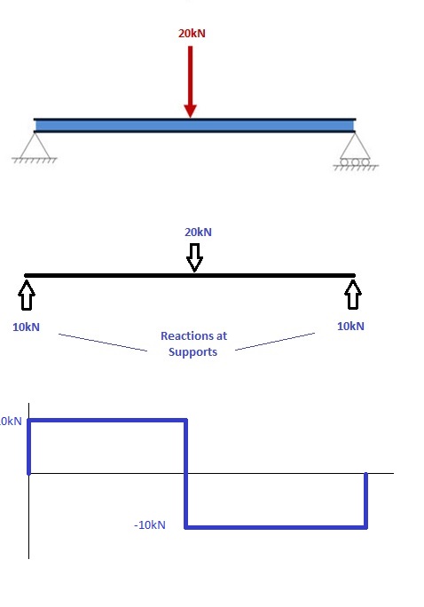
A free body diagram of a beam is shown above the shear and moment diagrams for that beam. Positive and negative internal bending moments To read the plot, you simply need to take the find the location of interest from the free body diagram above, and read the corresponding value on the y-axis from your plot.

Free body diagram beam
A crude outline of the beam is also shown to indicate that the configuration of the member is not important for finding out the reactions. The resultant force P acting though the centroid of the distributed forces is found out. Once a free body diagram is prepared, the solution is found out by applying the equations of static equilibrium. ∑ F ... Another example is in a log splitter where the cylinder is pressing (applying load) at the same fixed distance away from the beam axis. The load applied by the cylinder creates a constant moment along the entire length of the beam. Once you have your loads, create a free body diagram showing each load and where it occurs on the beam. It doesn ... Free-Body Diagram of Beam: The beam is supported by a pin at point A and a horizontal roller at point D. Therefore, there are two unknown reactions at point A and one at point D as shown below. Notice that in drawing the free-body diagram we assume a direction for each reaction load. The correctness or incorrectness of each assumed direction will be determined by solving for the magnitude of ...
Free body diagram beam. beam diagrams and formulas by waterman 55 1. simple beam-uniformly distributed load 2. simple beam-load increasing uniformly to one end ... 23. beam fixed at one end, free to deflect vertically but not rotate at other-concentrated load at deflected end 24. beam overhanging one support-uniformly distributed load. 25. beam overhanging one support ... Draw the beam free body diagram Replace the uniform distributed load (if any) with the equivalent point load Solve ΣM A = 0 (sum of moments about support A). This will give you R B (reaction at support B). Solve ΣM B = 0. This will give you R A. Using R A and R B found at steps 3 and 4 check if ΣV = 0 (sum of all vertical forces) is satisfied. For the beam and loading shown, (a) draw the shear and bending-moment diagrams, (b) determine the equations of the shear and bending-moment curves. SOLUTION Free body diagram for determining reactions. Reactions: 000: 0 22 yA A wL wL FR R 0: 00 2 23 AA wL L MM 00 22 33 A wL wL M Use portion to left of the section as the free body. FREE-BODY DIAGRAMS (Section 5.2) 2. Show all the external forces and couple moments. These typically include: a) applied loads, b) support reactions, and, c) the weight of the body. Idealized model Free-body diagram (FBD) 1. Draw an outlined shape. Imagine the body to be isolated or cut "free" from its constraints and draw its outlined shape.
A free body diagram is a graphic, dematerialized, symbolic representation of the body (structure, element or segment of an element) in which all connecting "pieces" have been removed. A FBD is a convenient method to model the structure, structural element, or segment that is under scrutiny. It is a way in which to conceptualize the ... https://goo.gl/P5AUbb for more FREE video tutorials covering Engineering Mechanics (Statics & Dynamics)The key objective of this video is to consider support... Free-Body Diagram See Fig. 3.21 (b). Static Determinacy The beam is internally unstable. It is composed of three rigid members, AB;BE, and EF, connected by two internal hinges at B and E. The structure has r =5 and ec = 2; because r =3 + ec, the structure is statically determinate. The remaining two equilibrium equations can now be applied to ... 33 Free Body Diagrams Wednesday, October 3, 2012 New Support Conditions Pin Connection ! The next type of connection is the pin or the smooth pin or hinge ! One way to think of this is to drive a nail through a ruler partway into a table top 34 Free Body Diagrams Wednesday, October 3, 2012 New Support Conditions Pin Connection !
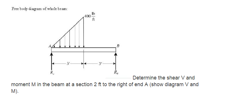
Steps: a. Sketch the free body diagrams of the beam showing all the loading and external reactions. b. Calculate the values of all external reactions. C. Draw the shear diagram under the free body diagram and moment diagram under the shear diagram. 1. Draw the complete shear and bending moment diagrams for the cantilever beam. 2N 152N 2. Any changes made will automatically re-draw the free body diagram any simply supported or cantilever beam. The beam reaction calculator and Bending Moment Calculations will be run once the "Solve" button is hit and will automatically generate the Shear and Bending Moment Diagrams. You can also click the individual elements of this LVL beam calculator to edit the model. 4.3 Shear- Moment Equations and Shear-Moment Diagrams The determination of the internal force system acting at a given section of a beam : draw a free-body diagram that expose these forces and then compute the forces using equilibrium equations. The goal of the beam analysis -determine the shear force V and The beam shown below is supported by a pin at A and roller at B. Calculate the reactions at both supports due to the loading. 20 kN 40 kN 2 m 3 m 4 m A B EXAMPLE 1 Draw the free body diagram: By taking the moment at B, ΣM B = 0 RAy × 9 - 20 × 7 - 40 × 4 = 0 9R Ay = 140 + 160 R Ay = 33.3 kN ΣF y = 0 R+ By-20 40 = 0 R By= 20 + 40 -33.3
Monochrome, Blaydon Bridge, Tyne & Wear, England.
From the free-body diagram of the beam (Fig. 8.3a), we find that the reactions at the supports are RA = 1 kN and Rc = 5 kN, respectively, and draw the corresponding bending-moment 396 diagram (Fig. 8.3b).

Solved: Draw The Free-body Diagram For The Beam. A Is A Ro ...
Once you have your loads, create a free body diagram showing each load and where it occurs on the beam. It doesn't have to be exactly to scale, but it helps if it is close. Be sure to leave room directly below the beam so that we can draw our shear-moment diagram!

35 Cantilever Beam Free Body Diagram - Wiring Diagram Database
https://goo.gl/vNKUHp for more FREE video tutorials covering Engineering Mechanics (Statics & Dynamics)The objectives of this video are to give an introducto...

Please donate. WebMoney: Z138632687735, R330729825060, skrill- alexfoto@bigmir.net, SWIFT - KRYVYTSKYI OLEKSANDR, BIC: PBANUA2X, IBAN: UA913052990005168745600778382, I will be glad information on the use of photos.
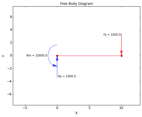
Free body diagrams may not seem necessary in the relatively simple current applications, but as problems become more complex, their usefulness increases. The following is the process for determining the reaction at the wall for a cantilever beam. A FBD is first drawn of the beam. Next, cut the beam free from the wall and replace the wall with the forces that were supporting the beam at the ...

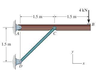
Free-body diagram of the beam AC. | Download Scientific ...
Free online beam calculator for generating the reactions, calculating the deflection of a steel or wood beam, drawing the shear and moment diagrams for the beam. This is the free version of our full SkyCiv Beam Software. This can be accessed under any of our Paid Accounts, which also includes a full structural analysis software.

31 Draw The Free Body Diagram For The Cantilevered Beam. A ...
Free-Body Diagram of Beam:The beam is supported by a pin at point A and a horizontal roller at point D. Therefore, there are two unknown reactions at point A and one at point D as shown below. Notice that in drawing the free-body diagram we assume a direction for each reaction load.
35 Cantilever Beam Free Body Diagram - Wiring Diagram Database
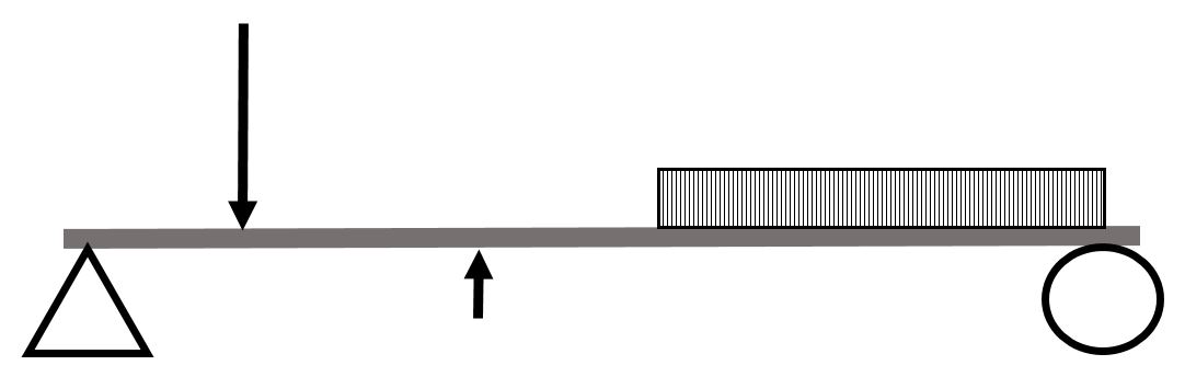
Since the forces act on the beam at different points, beam must be treated as an extended object and the forces in the free body diagram must come out of the appropriate location. The weight of the beam acts at its center of gravity (the geometric center). Since the beam is at rest, the net torque around ANY axis is zero.

SOUL TRAVEL IN YOUR LIGHT BODY...Astral Travel - the Stargate Aldebaran..I saw his presence in my mirror access a particular doorway, star system, or vortex.
BEAM GURU .COM is a online calculator that generates Bending Moment Diagrams (BMD) and Shear Force Diagrams (SFD), Axial Force Diagrams (AFD) for any statically determinate (most simply supported and cantilever beams) and statically indeterminate beams, frames and trusses.

Old Railway Bridge, Newcastle/Gateshead, Tyne & Wear, England.
Once you have the reactions, draw your Free Body Diagram and Shear Force Diagram underneath the beam. Finally calculating the moments can be done in the following steps: 2. From left to right, make "cuts" before and after each reaction/load To calculate the bending moment of a beam, we must work in the same way we did for the Shear Force Diagram.
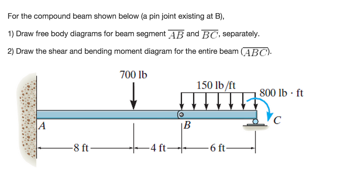
For The Compound Beam Shown Below (a Pin Joint Exi ...
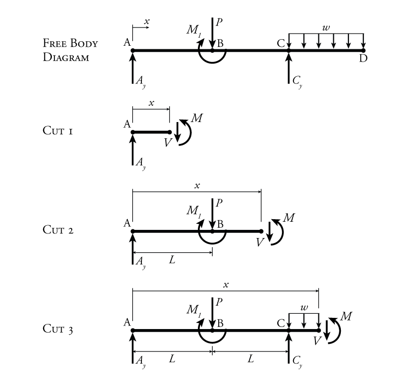
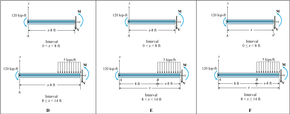
(Free Body Diagram) is drawn to determine the equations express-ing the shear and bending mo-ment in terms of the distance from a convenient origin. Plotting these equations produces the shear and bending moment diagrams.
Beam Reactions and Diagrams - Strength of Materials ...
The objectives of this video are to give an introductory overview on how to use free body diagrams to deduce support reactions followed by a comprehensive workout on support reactions example. At first, the video illustrates a given diagram of simply supported beam having a pin support at left end and a roller support at right end and consequently shows the point load conditions acting over ...

Go Kart Carburetor Diagram Beautiful Gy6 150cc Carb – Gy6 ...
Fig. 3.8 Normal force diagram for the beam of Ex. 3.1 When the equilibrium of a portion of a structure is considered as in Fig. 3.8(b) we are using what is termed a free body diagram. Example 3.2 Draw a normal force diagram for the beam ABC shown in Fig. 3.9(a). Again by considering the overall equilibrium of the beam we see that RA," = 10 kN

Beyond the Standard Model - STRINGS
A free body diagram of a shaft is shown above the corresponding toque diagram. Remember to use the right hand rule to determine if the moment vector is pointing to the right or left. To read the plot, you simply need to take the find the location of interest from the free body diagram above, and read the corresponding value on the y-axis from ...
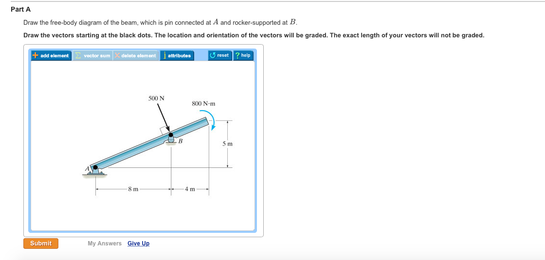
Solved: Part A Draw The Free-body Diagram Of The Beam, Whi ...
Free-Body Diagram See Fig. 3.21 (b). Static Determinacy The beam is internally unstable. It is composed of three rigid members, AB;BE, and EF, connected by two internal hinges at B and E. The structure has r =5 and ec = 2; because r =3 + ec, the structure is statically determinate. The remaining two equilibrium equations can now be applied to ...

Monochrome, Scotswood Bridge & Blaydon Railway Bridge, Tyne & Wear, England.
Free Beam Calculator for Statically Indeterminate Beams. Support Reactions. Shear Diagram. Moment Diagram. Indeterminate / Continuous Beams. Premium: Deflection and Stress Diagrams. Premium: Custom and Standard Sections or Materials. Premium: Save Unlimited Models and Sections. Premium: PDF Reports and Custom Logo.

Monochrome, Overhead Road, Blaydon, Tyne & Wear, England.
Free-Body Diagram of Beam: The beam is supported by a pin at point A and a horizontal roller at point D. Therefore, there are two unknown reactions at point A and one at point D as shown below. Notice that in drawing the free-body diagram we assume a direction for each reaction load. The correctness or incorrectness of each assumed direction will be determined by solving for the magnitude of ...

Free body diagram of interior columns and associated beam ...
Another example is in a log splitter where the cylinder is pressing (applying load) at the same fixed distance away from the beam axis. The load applied by the cylinder creates a constant moment along the entire length of the beam. Once you have your loads, create a free body diagram showing each load and where it occurs on the beam. It doesn ...

Statics eBook: Shear and Moment Diagrams I
A crude outline of the beam is also shown to indicate that the configuration of the member is not important for finding out the reactions. The resultant force P acting though the centroid of the distributed forces is found out. Once a free body diagram is prepared, the solution is found out by applying the equations of static equilibrium. ∑ F ...

Free-body diagram of tri-material (a) beam model and (b ...

(a) A cantilever under a concentrated load and (b) the ...
Solved: Part A - Reactions At Support C Draw A Free-body D ...
Example 5
Solved: Part 1. Draw The Free-body Diagram For The Truss ...

Solved: A) Draw The Free Body Diagram For The Beam. B) Det ...

Night Time, Water Reflection, Washington Monument, Washington, District Of Columbia, United States Of America.
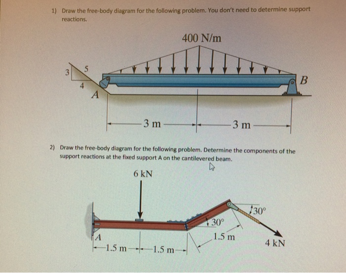
Solved: Draw The Free-body Diagram For The Following Probl ...
Solved: I Did A Free Body Diagram Splitting The Beam At Hi ...

9-Free body diagram of the left half of the deep beam DB-1 ...

classical mechanics - Bending moment in a cantilever beam ...

A well defined collarbone is hard to come by.
Mechanical Engineering Archive | January 26, 2017 | Chegg.com

Monochrome, Blaydon Railway Bridge, Tyne & Wear, England.
What are Free Body Diagrams?

Free-body diagram of one infinitesimal element of the ...
Solved: Draw A Free-body Diagram Of The Beam, Determine Th ...
Mechanical Engineering Archive | April 27, 2015 | Chegg.com
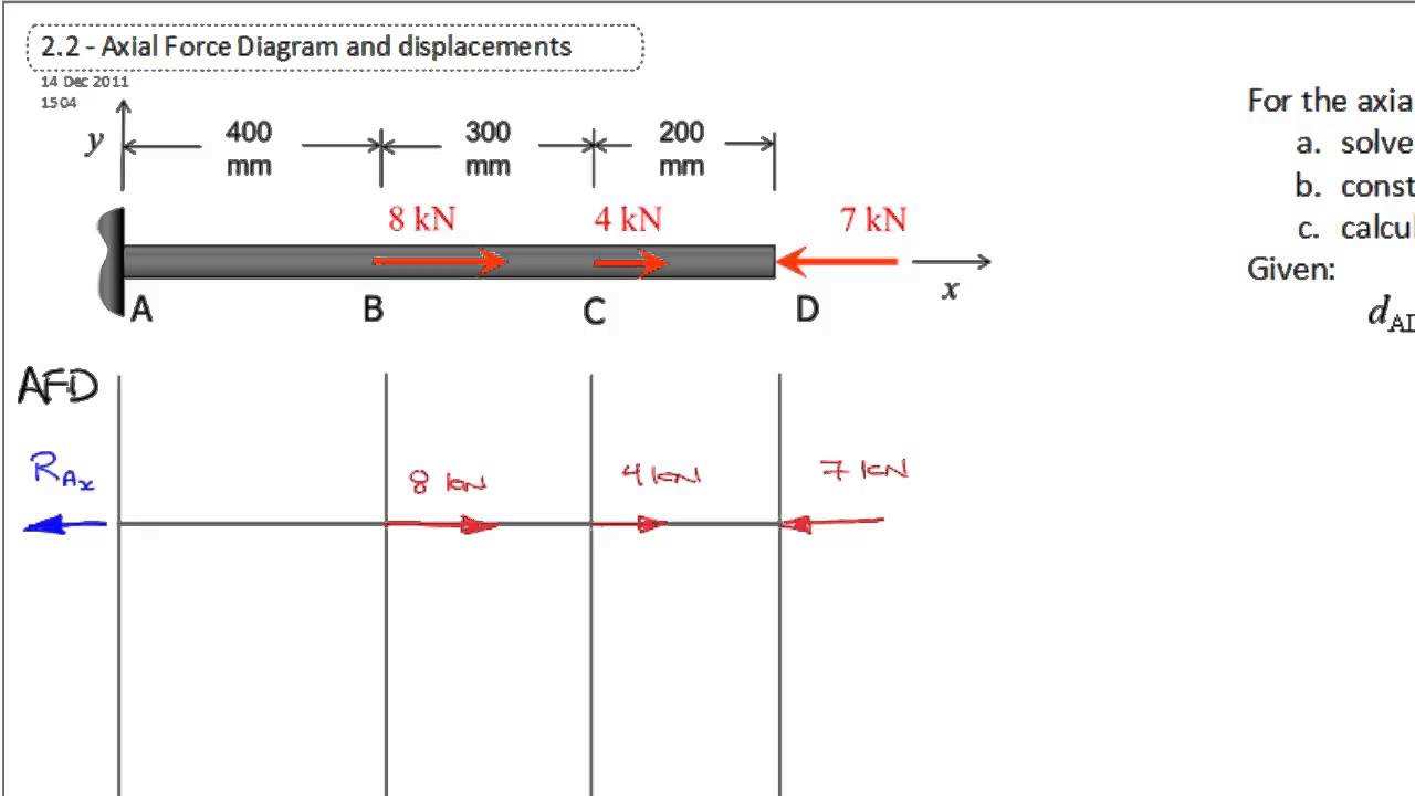
Axial Force Diagram (Reactions) - YouTube

Kyiv city fine art
Solved: Draw The Free-body Diagram Of The Beam Shown Below ...

3: Figure showing the free body diagram at the tip of the ...

What is Holistic Design?...The secret enfolded in the beauty of a building (or of any artifact) as a whole lies in its spatial order and in the nature of its details.
Draw The Free Body Diagram For The Beam A Is A Rocker And ...
2D Finite Element Analysis - Validation | MechaniCalc
How to Draw Bending Moment Diagrams | SkyCiv
Cantilever Beam Free Body Diagram - Hanenhuusholli
0 Response to "45 free body diagram beam"
Post a Comment