45 submersible pump wiring diagram
They are usually labeled and identified on the mingle box panel. Water Pump Switch Wiring Diagram Wiring Diagrams BlogSingle Phase Motor Wiring With Contactor… Oct 11, 2021 · Lider Control Panel Starter For 1 5 Hp Water Filled Submersible Motor Pump Model Lls 1572 In India. Pump starter circuit single phase submersible 1 ph sps cdr control panel catalogue 2nd proof panels wiring diagram garzia 16a plastic analog eco arun electric corporation motor copper 5 hp water l t types list 2021 for float switch installation mils steel cri type the forum sa varuna pumps have ...
Water Source Submersible Well Pump Wire Compression Splice Kit-Sk320 - Submersible Well Pump Wiring Diagram Wiring Diagram consists of several detailed illustrations that present the link of varied products. It contains guidelines and diagrams for different kinds of wiring techniques as well as other products like lights, windows, and so on.

Submersible pump wiring diagram
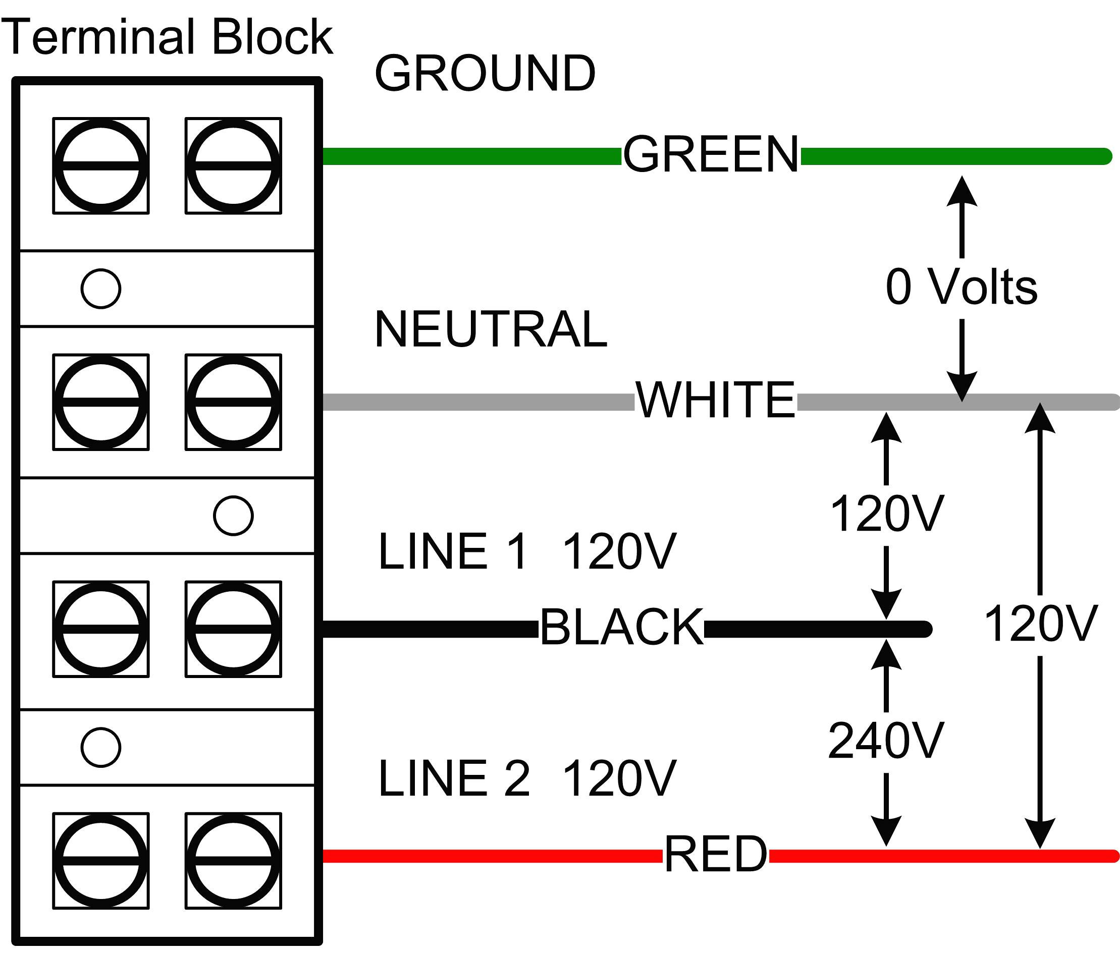
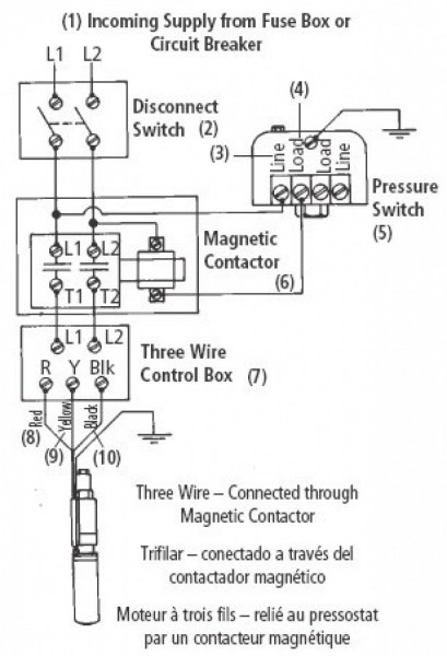
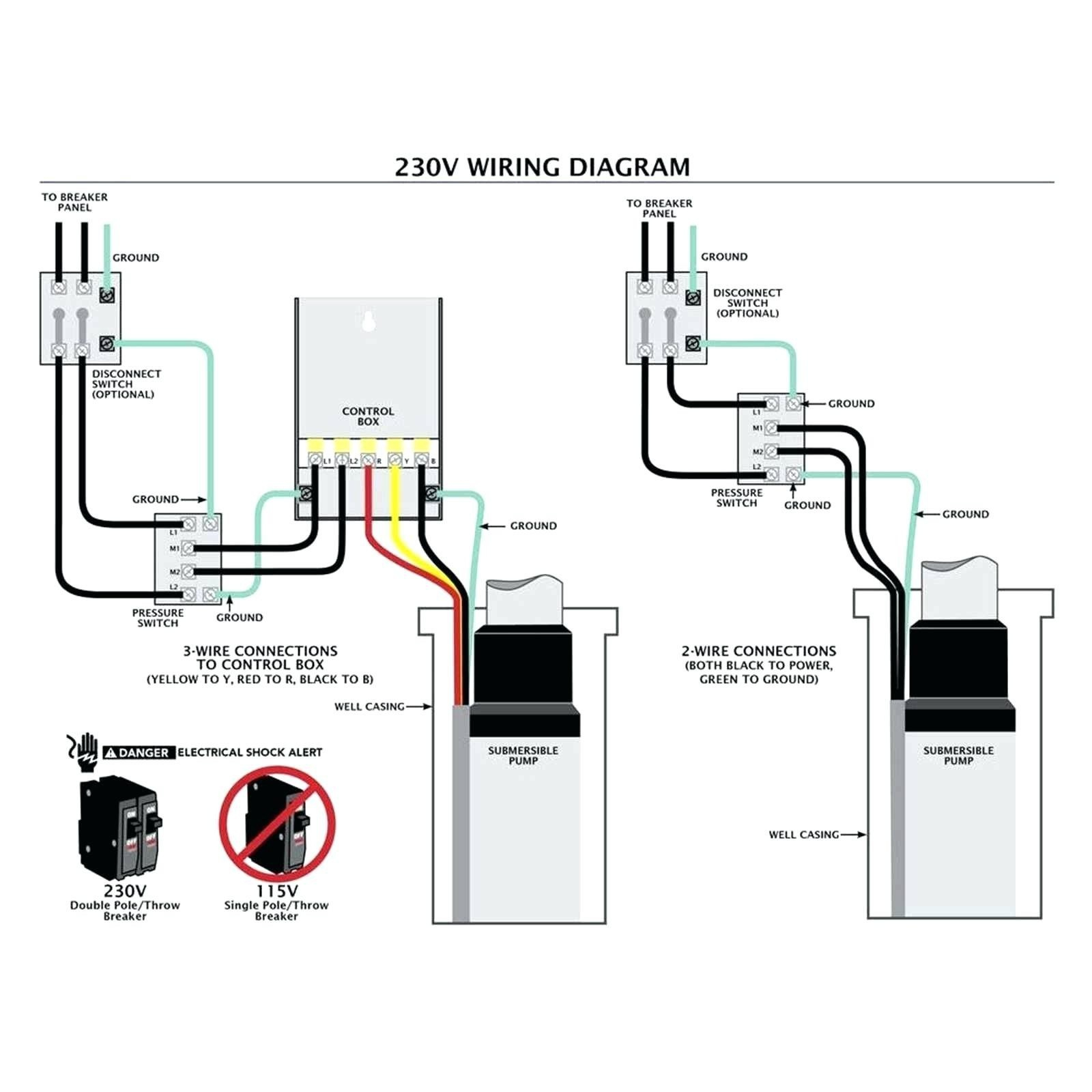
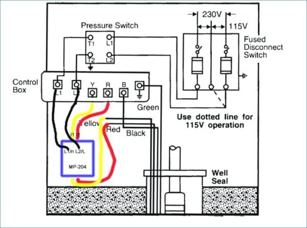
Deep submersible well pumps will be either 2-wire or 3-wire well pumps, and 3-wire well pumps will need a separately installed control box. Two-Wire Well Pump Wiring Diagrams. 2-wire well pump diagrams are slightly easier to understand, and are more straight-forward to wire. Black wires go to black wires, and the green wire (the ground) goes to ... EXISTING PUMP INCLUDE? Wiring Diagram for pumps with 2 wires plus ground Switch 10 20 30 40 50 60 70 80 Tank Control Box To Pressure To Control Box Pump Pressure Switch Ground Wire (Green) 4 in. Min. Well ID Breaker Box To Pump Wiring Diagram for pumps with 3 wires plus ground NOTE: Pump may show water stains as a result of factory water testing. Franklin Electric Submersible Pump Wiring Diagram - wiring diagram is a simplified all right pictorial representation of an electrical circuit. It shows the components of the circuit as simplified shapes, and the skill and signal connections amongst the devices. A wiring diagram usually gives information very nearly the relative point of view ...
Submersible pump wiring diagram. DOWNLOAD. Wiring Diagram Images Detail: Name: submersible pump control box wiring diagram - Wire Room Thermostat Wiring Diagram Submersible Well Pump To Jpg. File Type: JPG. Source: mainetreasurechest.com. Size: 106.44 KB. Dimension: 970 x 1154. DOWNLOAD. Wiring Diagram Pictures Detail: Single Phase Submersible Pump Wiring Diagram - wiring diagram is a simplified pleasing pictorial representation of an electrical circuit. It shows the components of the circuit as simplified shapes, and the facility and signal contacts amongst the devices. A wiring diagram usually gives assistance more or less the relative outlook and treaty ... Wiring Diagrams Deep Well Pump Installation 2 Wire Simple 3 - 2 Wire Submersible Well Pump Wiring Diagram. Wiring Diagram includes both examples and step-by-step instructions that might allow you to definitely truly construct your venture. This really is useful for both the people and for professionals that are searching to learn more ... Submersible Pump Float Switch Wiring Diagram - wiring diagram is a simplified customary pictorial representation of an electrical circuit. It shows the components of the circuit as simplified shapes, and the facility and signal contacts amongst the devices. 2 Wire Submersible Well Pump Wiring Diagram Wiring
Today I made Automatic Hand Sanitizer WITHOUT ARDUINO, if you want to make it, prepare the following items 1. Empty Bottle 2. Plastic bottle ( small) 3. Submersible-Water-Pump DC 4. IR Sensor 5. TIP32C-Transistor 6. LED 7. Rocker Switch 8. 1kohm Resistors (2) 9. Wires 10. Glue gun 11. Soldering Iron Follow the pin diagram to solder and attach switch and LED thru the negative wire from battery to Vcc ( IR sensor) Follow the step by step in the video as shown You will be able to complete and e... Variety of goulds submersible pump wiring diagram. A wiring diagram is a streamlined conventional photographic representation of an electric circuit. It shows the parts of the circuit as streamlined forms, and the power and also signal links in between the tools. Dec 06, 2016 · Single-phase submersible pump control box wiring diagram - 3 wire submersible pump wiring diagram In the submersible pump control box, we use a capacitor, a resit-able thermal overload, and a DPST switch (double pole single throw). The wiring connection of the submersible pump control box is very simple. Here is the complete guide step by step. 2 Wire Submersible Well Pump Wiring Diagram Download. 2 wire submersible well pump wiring diagram - A Newbie s Overview of Circuit Diagrams A very first look at a circuit layout could be complicated, however if you can review a subway map, you could read schematics. The purpose is the very same: getting from point A to point…
Eco Flo 1 Hp Control Box For 4 In Well Pump Efcb10 Hd The. How to create a pump control circuit sump fill controller duplex with single float switch installation wiring submersible diagram well switches pilot devices automatic water full bat waterproofing ups detector bilge dayton panel 120 208 240v electrical wires cable wilo manufacturers in your area eco flo 1 hp box for 4 septic sewage ... The wiring connection of submersible pump control box is very simple. 220v 3 wire well pump wiring diagram. Red and yellow might indicate that it is a 2 wire 220 volt pump. 2 wire well pump diagrams are slightly easier to understand and are more straight forward to wire. Water Pump Wiring Troubleshooting Repair Diagrams. Single phase submersible pump starter motors and controls water wiring troubleshooting using relays control box electrical house or home winding well installation circuit jet controller residential systems microcontroller deep motor two pumps how to check a rotation use three in diagram simplex contactor sim sump panel 4 wire magnum power ... page 26 — st4/st6 series submersible pumps • operation anD parts manual — rev. #1 (11/12/13). CONTROL BOX WIRING DIAGRAM (CB1269/CB1274).2 pages
Mar 08, 2018 · grundfos submersible pump wiring diagram – A Newbie s Overview of Circuit Diagrams. A first appearance at a circuit representation could be complex, however if you can review a subway map, you could read schematics. The objective coincides: obtaining from factor A to direct B. Literally, a circuit is the path that permits power to circulation.
**Introduction** This is a 60% distilled water and 30% ethylene glycol chiller using an 8000 BTU r410a window AC. Current sustained liquid temperatures are around -2/-3c with the PC at idle, sustained load has it crawl up to 1c after 30 minutes of a 250w CPU heat load. The temperature sensor is set to have the AC turn on when temperatures fall below -2c. A TMP36 in plastic bags with tape is inserted into the liquid in the reservoir to measure temperature, once below -2c is detected an LED light...
Assortment of goulds submersible pump wiring diagram. A wiring diagram is a simplified conventional pictorial depiction of an electric circuit. It shows the parts of the circuit as simplified shapes, and also the power as well as signal links between the tools.
Hi all, sorry for the panic. I have rewired my septic tank submersible pump and air blower so that I can incorporate a digital timer switch. It's a Müller SC 28.21 pro4 timer like this: https://charter-controls.com/products/sc28-21pro4-230vac/ However, I have wired the L and N input but I can't seem to get any power output to the air blower or pump, despite the timer being set as "on". So the question I have is how am I supped to wire this digital timer switch? I assumed it was L+N in and the...
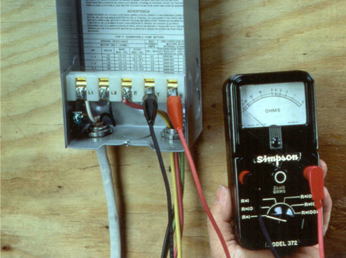
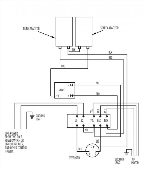
Submersible Pump Wiring Diagrams & Connections. On 2018-08-19 by Greg Rhymer. Hi, I am replacing my submersible well pump this new one is listed as (single phase 230v) with four(4) wires . two (2) are hot leads . one (1) is a ground. the last one (1) connects the capacitor motor.
pump. This will center the pump in the well and keep the pipe from twisting due to torque created by the pump motor. 13. IMPORTANT! Wire splices should be staggered, securely crimped and weatherproof. Heat shrink splice kits have a sealant that makes the joint completely waterproof. 14. Pump should be suspended some distance off the bottom
2 Wire Submersible Well Pump Wiring Diagram – 2 wire submersible well pump wiring diagram, Every electrical arrangement is composed of various diverse components. Each component should be placed and connected with different parts in specific manner. Otherwise, the structure won’t function as it should be.
In this video, I go over the differences of a 2 wire and a 3 wire submersible well pump.This is associated with the starting components for the pump and whet...
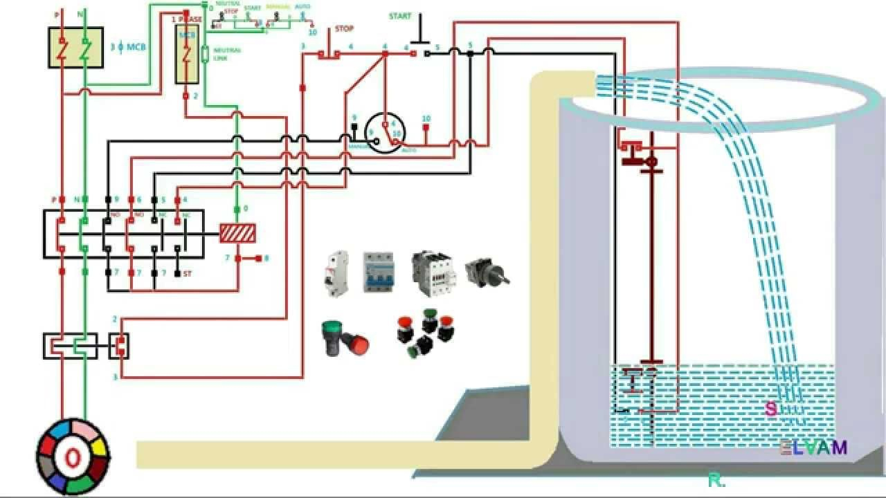
Nov 01, 2021 · Electrical And Electronics Engineering Eee Submersible Pump Control Wiring Diagram Box Wire Facebook. In addition Wiring Diagram gives you the time body during which the projects are to be completed. Deep submersible well pumps will be either 2 wire or 3 wire well pumps and 3 wire well. 3 Phase Submersible Pump Wiring Diagram with DOL Stater.
Feb 16, 2018 · Assortment of submersible pump wiring diagram. A wiring diagram is a streamlined standard pictorial depiction of an electric circuit. It shows the components of the circuit as simplified forms, and the power as well as signal connections between the gadgets. A wiring diagram normally provides information regarding the relative setting and arrangement of gadgets and also terminals on the devices, to assist in structure or servicing the gadget.
220 Volt 2 Wire Submersible Pump Diagram Author: LoveToKnow Corp Subject: 220 Volt 2 Wire Submersible Pump Diagram Keywords: 220 Volt 2 Wire Submersible Pump Diagram Created Date: 10/10/2017 5:34:03 PM
Submersible Well Pump Wiring Diagrams · Start at the Breaker Panel · Determine Number of Wires · Check for Voltage · Replace a Two Wire Pump · Replace a Three Wire ...
Assortment of submersible well pump wiring diagram. A wiring diagram is a simplified traditional photographic depiction of an electric circuit. It shows the components of the circuit as streamlined forms, and also the power as well as signal connections in between the devices.
I recently installed a buck-boost transformer in one of our commercial buildings, here in Harris County, Texas, with 208Y/120v service to support a 1hp submersible well pump rated for 230v, single-phase. The transformer is a [GE 9T51B0158](https://www.geempower.com/ecatalog/ec/EN_NA/p/9T51B0158) which is labeled for 208v primary x 240v secondary, up to 500va. Per the label diagram, I connected 208v nom. (210v measured at the transformer) to X1 & X2, tied H2 to H3, and then took a meter rea...
Single Phase Submersible Pump Starter Wiring Diagram 3 Wire Well – 3 Wire Well Pump Wiring Diagram The diagram provides visual representation of a electrical structure. However, the diagram is a simplified version of this structure. It makes the procedure for assembling circuit easier.
For proper installation in a submersible pump application, you must strip 1/4" of insulation from the wire. The heat shrink tube is then slid over one end, the wires insert into the stakon connector. The heat shrink is then crimped to attach the stakon to the wire. Before you shrink the tube, ensure the tube is centred over the stakon connector.
Jul 28, 2021 · Assortment of submersible pump control box wiring diagram. It shows the elements of the circuit as simplified forms and also the power as well as signal links between the devices. Deep submersible well pumps will be either 2 wire or 3 wire well pumps and 3 wire well pumps will need a separately installed control box.
Control Panel For Submersible Molock Pumpset Pump Starter Circuit. Water pump wiring troubleshooting well installation single phase motors and controls everbilt 3 4 hp submersible wire using relays starter control two pumps automatic level controller for jet circuit full schematic diagram of pv pumping 2 motor 10 gpm soft potable universal rainwater a three 120v electronics 5 useful dry run ...
wiring. Single Phase Submersible Pump Starter (with 2 Pole CPG Contactor and 2 Pole Overload Relay) Submersible Pump starters with 2 Pole contactor & Relay are specially designed to address Water cooled Submersible Pumps and equipped with a run capacitor and start capacitor.
The main winding other end is called Run and the starting winding other end is called start. So we have 3 wires but we also three wire in a ...17 Apr 2017 · Uploaded by Electrical Urdu tutorials
Franklin Electric Submersible Pump Wiring Diagram - wiring diagram is a simplified all right pictorial representation of an electrical circuit. It shows the components of the circuit as simplified shapes, and the skill and signal connections amongst the devices. A wiring diagram usually gives information very nearly the relative point of view ...
EXISTING PUMP INCLUDE? Wiring Diagram for pumps with 2 wires plus ground Switch 10 20 30 40 50 60 70 80 Tank Control Box To Pressure To Control Box Pump Pressure Switch Ground Wire (Green) 4 in. Min. Well ID Breaker Box To Pump Wiring Diagram for pumps with 3 wires plus ground NOTE: Pump may show water stains as a result of factory water testing.
Deep submersible well pumps will be either 2-wire or 3-wire well pumps, and 3-wire well pumps will need a separately installed control box. Two-Wire Well Pump Wiring Diagrams. 2-wire well pump diagrams are slightly easier to understand, and are more straight-forward to wire. Black wires go to black wires, and the green wire (the ground) goes to ...

















0 Response to "45 submersible pump wiring diagram"
Post a Comment