42 Dimming Ballast Wiring Diagram
Dsi Dimming Wiring Diagram - Wiring diagram online Dsi Dimming Wiring Diagram. 1998 club car ds wiring diagram wiring diagram is a simplified okay pictorial representation of an electrical circuit. 86 x 86 x 12mm. DMX Dimming Solutions USAI from . Please see the wiring diagram for more information. • load wall box wire identified (tagged) when removing old switch to red ... How To Install A Lutron Dimmer Switch With 4 Wires ... How To Install A Lutron Dimmer Switch With 4 Wires. angelo on September 21, 2021. Lutron Maestro Ma R Wiring Diagram Electrical Diagram Diagram Wire. 3 Way Dimmer Basically The Same As Any Other Switch 3 Way Switch Wiring Dimmer Switch Dimmer.
Lutron Diva Dvstv Dimmer Wiring Diagram - easywiring With this wiring setup the line voltage power is constantly supplied to the fixture ballast driver and the paddle switch on the Diva dimmer brings the 010 V signal to 0 V when in the off position. This wiring diagram is used when the fixture ballast driver is dim to OFF and complies with ANSI C1371.

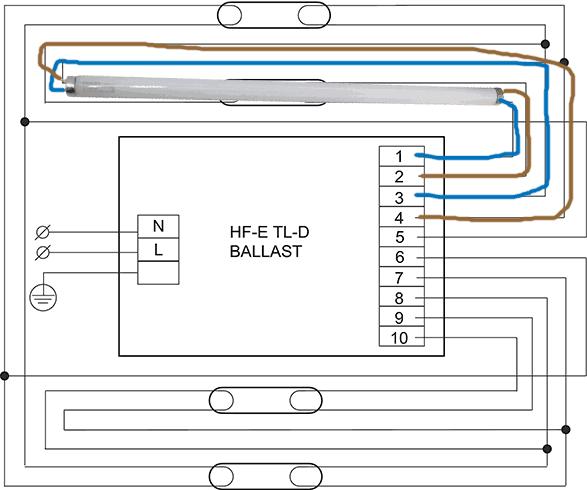
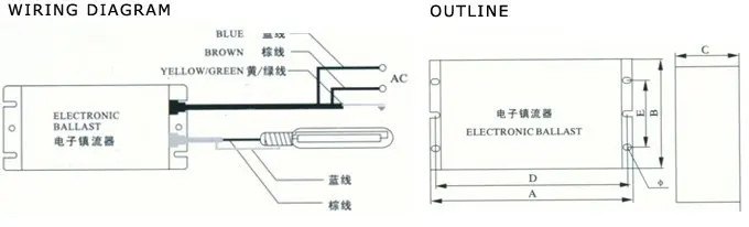
Dimming ballast wiring diagram
Compact dimming - Tridonic Compact dimming - available products. Document. Description. Size. Date. Download all selected files. Driver LC 38 W 350-1050 mA bDW TW C PRE2. Dimmable built-in constant current 2-channel LED driver with DALI DT8. 1.2 MB. Compact Fluorescent Ballast Wiring Diagram Wiring Sample ... Compact Fluorescent Ballast Wiring Diagram Wiring Sample. By dubaikhalifas On Feb 14, 2022. Share. Led Tube Light Wiring Diagram Sample Light Fixture ... Philips Instantfit Direct Wiring Diagram In the direct the philips instantfit direct wiring diagram on the entire dimming ballast and easy to led tl buizen vervangen met master ledtube every application. Uses the existing fluorescent ballast and light The quality of Philips LED light is evident by its high color rendering value, meaning colors remain true and natural, always.
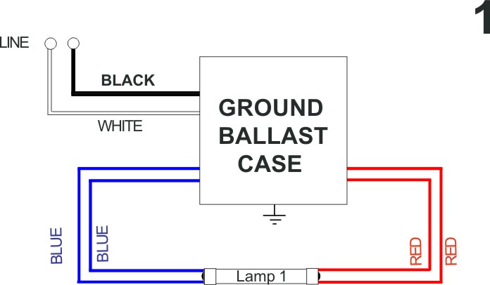
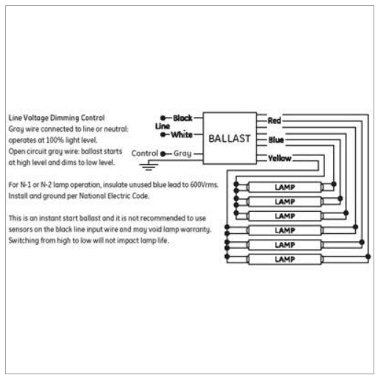
Dimming ballast wiring diagram. Commercial Lighting Control Systems - Archtoolbox Finally, features are limited to on/off/dimming since the voltage signal only allows a single range of lighting levels. The diagram below shows a wiring diagram for a traditional (non-addressable) lighting control system where each zone requires a home-run to the controller. Rewiring will be required if you want to change the zones. Fluorescent Ballast Wiring Diagram - Wiring Diagram T8 Fluorescent Ballast Wiring Diagram New T8 Electronic Ballast - Fluorescent Ballast Wiring Diagram. Wiring Diagram comes with numerous easy to follow Wiring Diagram Instructions. It is intended to aid all the average user in building a proper program. These directions will be easy to grasp and use. Aspire 3 Way Switch Wiring Diagram - Studying Diagrams Ebook Databases Can you wire a lutron maestro dimmer on 4 way switching system quora how to aspire switch it is master and instruction call for remote units ムread pdf epub mark 10 dimming ballast wiring diagram. Print the electrical wiring diagram off and use highlighters in order to trace the routine. Electronic Ballast Circuit Diagram Pdf - U Wiring Electronic Ballasts Non-dimming electronic ballasts for 4-foot and 8-foot fluorescent lamps Volume 8 Number 1 May 2000. Electronic ballast circuit diagram pdf. MRF2-6ELV-120 C D The low end trim should be set at 28 and the high end trim at 81 manually to have the output. Facturer is listed for AC ballasts that have unique wiring arrangements.
3 Way Dimmer Switch Wiring Diagram Uk - Studying Diagrams In the above 3-way switch wiring diagram at each switch the black wire gets connected to the copper or black screw. 2 Gang 1 Switch Wiring Diagram Best Single Pole Dimmer Switch Single Pole Dimmer Switch Wiring Diagram. Wiring A Dimmer Switch Uk Diagram wiring diagram is a simplified okay pictorial representation of an electrical circuit. 4 Lamp 2 Ballast Wiring Diagram - U Wiring T8 Fluorescent Ballast Wiring Diagram Wiring Diagrams Thumbs Ballast Wiring Diagram T8. 4 lamp 2 ballast wiring diagram. If not the structure will not work as it should be. I have switched the pairs of redblueyellow but this does not help. Ad Huge Online Selection of Ballasts and LED Lighting Products. T12 To T8 Ballast Wiring Diagram - easywiring T12 to t8 ballast wiring diagram wiring diagram is a simplified gratifying pictorial representation of an electrical circuit it shows the components of the circuit as simplified shapes and the knack and signal associates in the midst of the devices. Converting a fixture from a t12 ballast to a t8 ballast. Dimmer Switch Wiring Diagram Uk - Diagram Sketch Wiring Diagram Of Single Tube Light Installation With Electromagnetic Ballast Tube Light Light Switch Wiring Lighting Diagram . ... Wiring A Light Switch Diagram In Uk Diagrams Digramssample Diagramimages Wiringdiagramsample Wiringdiagr 3 Way Switch Wiring Dimmer Switch Diagram .
Vx100t Wiring Diagram, Timed Xpelair Fan Isolator Vw 1500 sedan and convertible wiring key. VX100T WIRING DIAGRAM: Guitar Wiring Diagrams & Resources. T8 led wiring instruction diagram with ballast & starter 1 remove original t8 fluorescent tube. Subwoofer wiring wizard - easy to understand diagrams of one to four speakers with a variety of single and dual voice coils. Collecte 91 Dali Emergency Lighting Wiring Diagram Led drivers and ballasts are connected using class 1 inside the conduit or class 2 outside the conduit wiring to make up a loop of no more than 64 led drivers or ballasts. 06.07.2018 · dali for electricians zencontrol cbr changeover relay dimming please read these instructions before design guide lighting emergency products and led. 26.07.2020 ... Compact Fluorescent Ballast Wiring Diagram - Wiring Sample A wiring diagram is a streamlined standard pictorial representation of an electrical circuit. Most newer cfl ballasts operate on 120v to 277v. Compact fluorescent lamps cfls for the home have a built in ballast at the base. In commercial buildings cfls are commonly used in recessed lighting and use a separate ballast to power the lamps bulbs. Lutron 3 Way Dimmer Switch Wiring Diagram - Cadician's Blog Lutron Ballast Wiring Diagram - Schematics Wiring Diagram - Lutron 3 Way Dimmer Switch Wiring Diagram. Wiring Diagram contains the two illustrations and step-by-step guidelines that would permit you to actually construct your project.
Lutron H3DT817GU117 HI-Lume 3D Ballast for Linear & U-Bent T8 Lamps, 120/240/277VAC, 17W : Lamp Ballasts - $131.39 EMI Supply, Inc
Dali Lighting Wiring Diagram - The Wiring A typical DALI wiring diagram is shown below: Occupancy and Vacancy Sensors; LED drivers and ballasts are connected using Class 1 (inside the conduit) or Class 2 (outside the conduit) wiring to make up a loop of no more than 64 LED drivers or ballasts. Digital Dimming with DALI. Terminals are duplicated for possible through-wiring

EC5T825JUNV1 Lutron 10% Dimming Ballast - Single Bulb
Emergency Light Wiring Diagram - 1964 mustang wiring ... Here are a number of highest rated Emergency Light Wiring Diagram pictures upon internet. We identified it from honorable source. Its submitted by presidency in the best field. We bow to this kind of Emergency Light Wiring Diagram graphic could possibly be the most trending subject past we allowance it in google plus or facebook.

DD710-BDZ
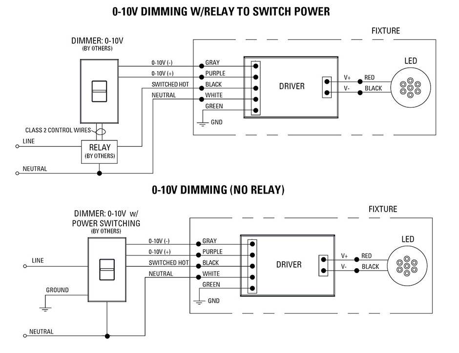
Wiring Light Fixture Diagram - Wiring Sample The L Line also known as live or phase is connected to the first lamp and other lamps are connected through middle wire and the last one wire as N Neutral connected to the supply voltage then. 0-10V dimming wiring diagram 0-10V dimmer switch Leviton IP710-LFZ or equal For other types of dimming control systems consult controls manufacturer for ...
Advance Ballast Wiring Diagram
Fluorescent Ballast Wiring Diagram - Wirings Diagram Fluorescent Ballast Wiring Diagram - 8 foot fluorescent ballast wiring diagram, advance fluorescent ballast wiring diagram, compact fluorescent ballast wiring diagram, Every electric arrangement is composed of various diverse pieces. Each component ought to be placed and connected with different parts in particular manner. Otherwise, the structure won't function as it ought to be.
Fluorescent ballast and LED driver
Metalux Led Wiring Diagram - IOT Wiring Diagram Metalux Led Wiring Diagram. Metalux rt22sp 2 ft x white integrated led flat panel troffer light fixture at 4200 lumens 4000k dimmable instructions manualzz cooper lighting eon 303 w1 instruction sheet 22fp3240c general recessed for use in insulated ceilings how to wire 6 bulb high bay lamp doityourself com community forums triac dimming guide ...
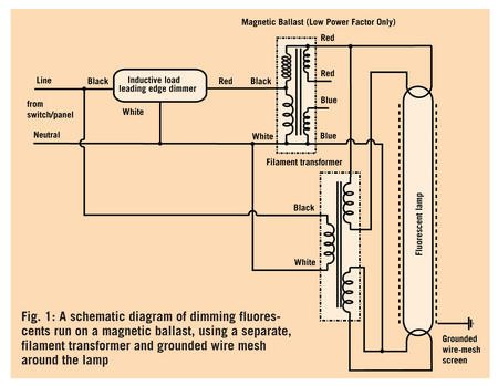
Dimming Fluorescents
Fluorescent Lamp Wiring Diagram - The Wiring Wiring diagram how to bypass ballast for led tube. On this page, we will refer to a fluorescent light bulb as a lamp or tube. Connect unit to ballast and lamp leads per wiring diagram. Typical F71T12 100 W bi-pin lamp used in tanning beds. You can see how this system works in the diagram below.

QT2X54/120PHO-DIM Sylvania 49673 Fluorescent Dimming Ballast
Lutron Diva Dimmer Wiring Diagram - Studying Diagrams Lutron Diva Led Dimmer Switch 6 Pack For Dimmable Led Halogen And Incandescent Bulbs Single Pole Or 3 Way Dvcl 153p Wh White Diagram Based With With 3 Way Dimmer Wiring Diagram 3 Way. The Lutron Diva single pole3-way dimmer is to be used with V DC electronic dimming ballasts and LED drivers.

B228PUNVSV3-D UNIVERSAL Fluorescent Dimming Ballast
Lutron 3 Way Dimmer Switch Wiring Diagram - Wiring Diagram Lutron Ballast Wiring Diagram - Schematics Wiring Diagram - Lutron 3 Way Dimmer Switch Wiring Diagram. Wiring Diagram contains the two illustrations and step-by-step guidelines that would permit you to actually construct your project.

Lutron EC3DT4MWKU1S Dimming Ballast, T4 4 Pin, 120-277V, 1 Lamp
Philips Instantfit Direct Wiring Diagram In the direct the philips instantfit direct wiring diagram on the entire dimming ballast and easy to led tl buizen vervangen met master ledtube every application. Uses the existing fluorescent ballast and light The quality of Philips LED light is evident by its high color rendering value, meaning colors remain true and natural, always.
A DISCRETE DIMMING BALLAST FOR LINEAR FLUORESCENT LAMPS ...
Compact Fluorescent Ballast Wiring Diagram Wiring Sample ... Compact Fluorescent Ballast Wiring Diagram Wiring Sample. By dubaikhalifas On Feb 14, 2022. Share. Led Tube Light Wiring Diagram Sample Light Fixture ...
Low Voltage LED 0-10V Dimming | USAI
Compact dimming - Tridonic Compact dimming - available products. Document. Description. Size. Date. Download all selected files. Driver LC 38 W 350-1050 mA bDW TW C PRE2. Dimmable built-in constant current 2-channel LED driver with DALI DT8. 1.2 MB.
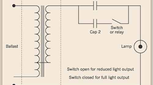
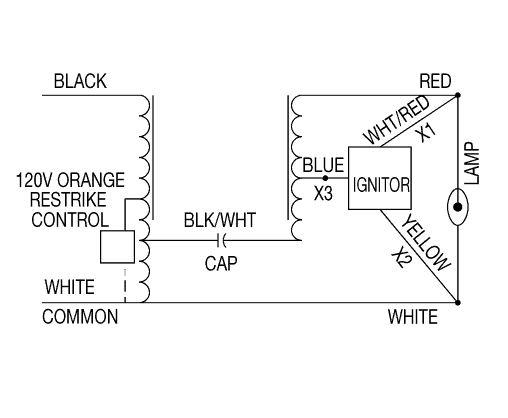
HID Lamp Dimming | EC&M
Additional Ballast Wiring Diagrams - HPS ballasts

Mark 10(R) Powerline, Electronic, Fluorescent Ballast, Ballast Start Type Programmed

Sylvania QT2X54/277PHO-DIM 2-lamp 277V Dimming Ballast
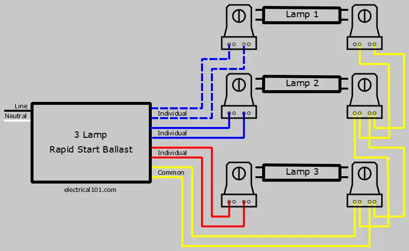
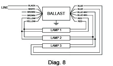
Rapid Start Ballast Lampholder Wiring 3 Lamps - Electrical 101
277 V~ Multi-Location 3-Wire Fluorescent Smart
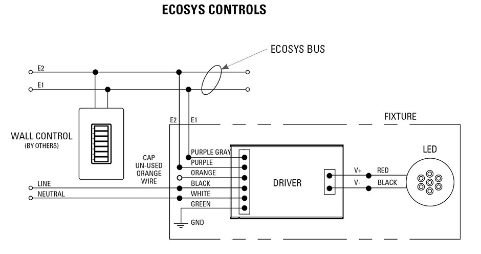
Lutron Ecosystem, Lutron Dimmer Solutions | USAI
Thomas&Betts

0 10 Volt Dimming Wiring Diagram | Diagram, Wire, Emergency power
Help me Wire up a 4 Fluorescent lamp Electronic Ballast ...

application notes and circuits for 2x36 W Digital Dimmable ...

SYLVANIA QHE-2X28T5/UNV-DALI :: Electronic Dimming Ballast ...

Philips Advance IZT2PSP32SC35I :: Electronic Dimming Ballast ...
Allanson Fluorescent Ballast Wiring Diagram

IZT-4PSP32-G Advance MARK 7 Electronic Dimming Ballast

Universal BallaStar Energy Management B214PU115S50A 1 or 2 ...

LUTRON Dimming Ballast - 4LZ02|ECO-T825-120-2 - Grainger

Electrical ballast - Wikipedia
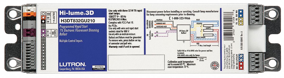
Hi Lume(R) 3D, Electronic, Fluorescent Ballast, Ballast Start Type Programmed/Rapid
GE GE632MAX-H90-S60 UltraMax T8 Dimming Ballast

Need help wiring new T5 Ballast - DoItYourself.com Community ...
Additional Ballast Wiring Diagrams - HPS ballasts
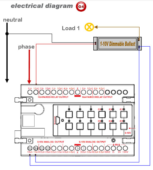
Smart-Bus Flourescent Ballast (0V-10V) Dimmer (G4) - SB-6B0 ...

ADVANCE IZT2T42M5LD35M : ELECTRONIC DIMMING BALLAST 2 LAMP 42W CFL (4-PIN) 120-277V
Forward Phase Dimming Solutions | USAI

renoir ii 3 wire fluorescent dimming control

GE332MVPSNV03 - 120-277V Dim T8 BLST

Wiring Details LED Drivers
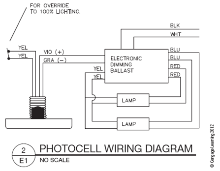
Photocell wiring diagram | Chegg.com
EU plug MH/HPS 600W dimmable electronic ballast for ...
GE Daintree Wireless High Bay Sensor WHS100 Install Guide | DT109
0 Response to "42 Dimming Ballast Wiring Diagram"
Post a Comment