41 cantilever beam free body diagram
Cantilever Beam - Point Load and Bending Moment at Free End Mar 09, 2022 · The above beam design and deflection equations may be used with both imperial and metric units. As with all calculations/formulas care must be taken to keep consistent units throughout with examples of units which should be adopted listed below: Notation. FBD = free body diagram; SFD = shear force diagram; BMD = bending moment diagram Beam Calculations Made Easy - From Free Body to Stress ... Another example is in a log splitter where the cylinder is pressing (applying load) at the same fixed distance away from the beam axis. The load applied by the cylinder creates a constant moment along the entire length of the beam. Once you have your loads, create a free body diagram showing each load and where it occurs on the beam.
Force Calculations - mathsisfun.com Free Body Diagram: A sketch where a ... Brady stands on the edge of a balcony supported by a horizontal beam and a strut: He weighs 80kg. What are the forces? Let's take the spot he is standing on and think about the forces just there: His Weight. His 80 kg mass creates a downward force due to Gravity. Force is mass times acceleration: F = ma. The acceleration due to gravity …

Cantilever beam free body diagram
6.2 Shear/Moment Diagrams – Engineering Mechanics: Statics Calculate the reactions using the equilibrium equations (may not need to do this if choosing a cantilever beam and using the free side for the FBD). Make a cut and add internal forces N V and M using the positive sign convention. Depending on the number of loads, you may need multiple cuts. Recall the positive convention: For shear, find an equation (expression) of the … Everything You Should Know About Cantilever Beams - The ... Figure-3: Bending and Shear Force Diagram of Cantilever Beam with Point Load at Free End The shear force at the fixed support A is determined by keeping the section at A, which gives the shear force Ra=W; and moment Ma = W.l. based on which the shear force and bending moment diagram are developed. PDF 3. BEAMS: STRAIN, STRESS, DEFLECTIONS The beam, or ... Cantilever beams and simple beams have two reactions (two forces or one force and a couple) and these reactions can be obtained from a free-body diagram of the beam by applying the equations of equilibrium. Such beams are said to be statically
Cantilever beam free body diagram. Cantilever Free Body Diagram Example | Statics - YouTube for more FREE video tutorials covering Engineering Mechanics (Statics & Dynamics)The key objective of this video is to consider support... Answered: Problem: Draw SFD and BMD, and obtain… | bartleby 14/03/2022 · Solution for Problem: Draw SFD and BMD, and obtain the maximum shear force and bending moment value for the beam shown: Load intensity is 100 N/m. -2 m 2 m- 2 m Solved For the cantilever beam loaded as shown, draw a free ... For the cantilever beam loaded as shown, draw a free body diagram and solve for all reactions, draw the shear and moment diagram and label all important features of the diagrams including slope, area, max and min, degree of curves. Show all your work. Write the equation for the internal shear and moment as a function of x for segments AB and BC. PDF T The Free Body AB Diagram The Concurrent System Beam Free Body Diagram. Actual Structure - A Truss Free Body Diagram. RIGID BODY SYSTEMS ASimple Supported Beam A Cantilever Beam. A Mast with a Platform ... A simply supported beam A simply supported beam. A Beam Supported by a Column and a Knee Frane Hinged cantilever beam with cable support. Examples from Bio-Medical Engineering - Human ...
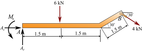
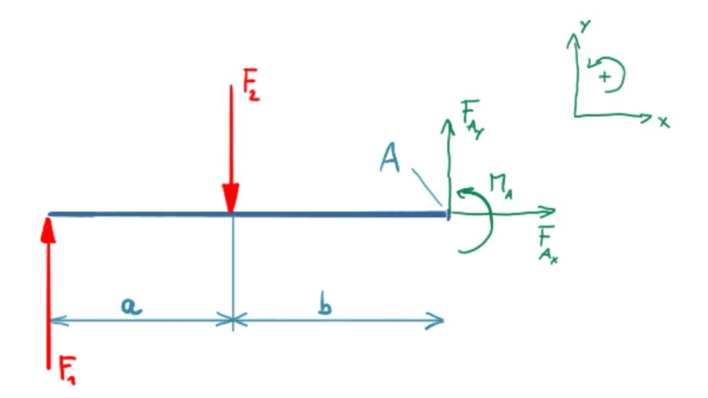
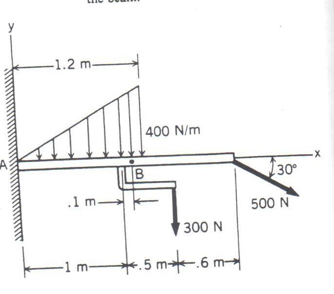
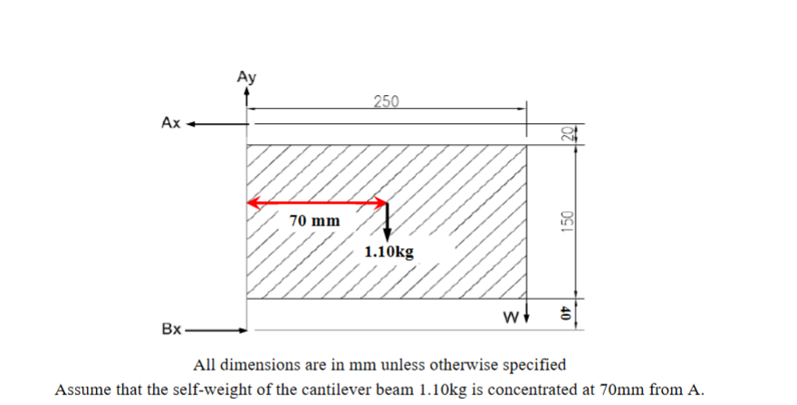
1.3: Equilibrium Structures, Support Reactions ... 05/03/2021 · A cantilever beam is subjected to a uniformly distributed load and an inclined concentrated load, as shown in figure 3.9a. Determine the reactions at support A. Fig. 3.9. Beam. Solution. Free-body diagram. The free-body diagram of the entire beam is shown in Figure 3.9b. The support reactions, as indicated in the free-body diagram, are A y, A x, and M. … Beam Reactions and Diagrams - Strength of Materials ... Draw the beam free body diagram Replace the uniform distributed load (if any) with the equivalent point load Solve ΣM A = 0 (sum of moments about support A). This will give you R B (reaction at support B). Solve ΣM B = 0. This will give you R A. Using R A and R B found at steps 3 and 4 check if ΣV = 0 (sum of all vertical forces) is satisfied. Example 6: For the cantilever beam and loading shown ... Free-Body Diagram of Beam: The beam is fixed at point A. Therefore, there are two reaction forces and one reaction moment at this point as shown below. We assume a direction for each reaction load. Also to simplify the calculations, the distributed force is represented by its resultant acting at its centroid., Mechanics of Materials by Andrew Paytel - Academia.edu Download Free PDF. Download Free PDF. Mechanics of Materials by Andrew Paytel. Md Atiqur Rahman. Download Download PDF. Full PDF Package Download Full PDF Package. This Paper. A short summary of this paper. 21 Full PDFs related to this paper. Read Paper. Download Download PDF. Download Full PDF Package ...
(a) Cantilever beam model; (b) free-body diagram; (c) a ... Download scientific diagram | (a) Cantilever beam model; (b) free-body diagram; (c) a section of beam from publication: INPUT SHAPING CONTROL TO REDUCE RESIDUAL VIBRATION OF A FLEXIBLE BEAM | In ... Free body diagram of the three segments of the cantilever beam. Download scientific diagram | Free body diagram of the three segments of the cantilever beam. from publication: Large deflection of cantilever beams with geometric non-linearity: Analytical and ... Cantilever Beam | It's Complete Overview and important ... The Free body diagram for the cantilever beam is drawn below: Free body diagram Cantilever beam boundary conditions The reaction Forces and moment at A can be calculated by applying Equilibrium conditions of \sum F_y=0, \sum F_x=0 ,\sum M_A=0 For horizontal Equilibrium \sum F_x=0 R_ {HA}=0 For vertical Equilibrium Cantilever Beam - UDL and End Bending Moment The above beam design and deflection equations may be used with both imperial and metric units. As with all calculations/formulas care must be taken to keep consistent units throughout with examples of units which should be adopted listed below: Notation. FBD = free body diagram; SFD = shear force diagram; BMD = bending moment diagram
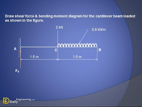
Shear Force and Bending Moment Diagram for Cantilever Beam ...
PDF University of California, Berkeley Using the free-body diagram of the portion AC of the beam (Fig. 8.8), where C is located at a distance x from end A, we find (8.7) Substituting for M into Eq.. (8.4) and multiplying both members by the constant El, we write d 29' El Integrating in F, we obtain The deflection and slope at A are obtained by letting — O in Eqs. (8.11) and (8.9).

Draw the moment diagram for the cantilevered beam. | Study.com
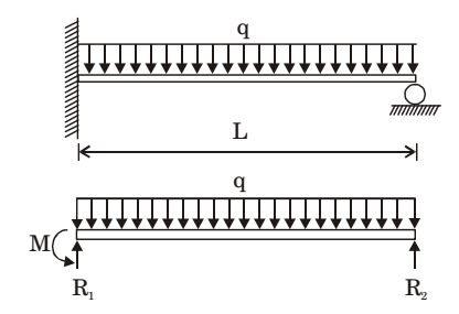
A uniformly loaded propped cantilever beam and its free ... Question. Download Solution PDF. A uniformly loaded propped cantilever beam and its free body diagram are shown below. The reactions are. R 1 = 5 q l 8, R 2 = 3 q l 8, M = q l 2 8. R 1 = 3 q l 8, R 2 = 5 q l 8, M = q l 2 8. R 1 = 5 q l 8, R 2 = 3 q l 8, M = 0. R 1 = 3 q l 8, R 2 = 5 q l 8, M = 0.
Shear Force and Bending Moment Diagram for Cantilever Beam ...
Mechanics Map - Bodies and Free Body Diagrams Free Body Diagrams. A free body diagram is a tool used to solve engineering mechanics problems. As the name suggests, the purpose of the diagram is to "free" the body from all other objects and surfaces around it so that it can be studied in isolation. ... 100 lb cantilever beam. Assume the beam is firmly anchored to the wall. Draw a free body ...
Solved: Chapter 5 Problem 1P Solution | Engineering Mechanics ...
What are Free Body Diagrams? - Massachusetts Institute of ... Free body diagrams may not seem necessary in the relatively simple current applications, but as problems become more complex, their usefulness increases. The following is the process for determining the reaction at the wall for a cantilever beam. A FBD is first drawn of the beam. Next, cut the beam free from the wall and replace the wall with ...
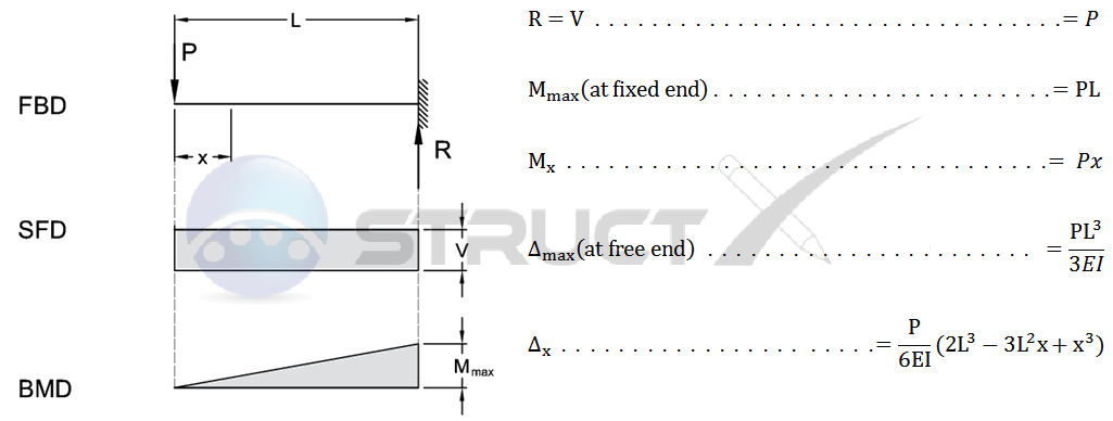
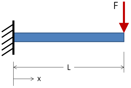
Cantilever Beam - Point Load at Free End
How to Draw a Free Body Diagram - Simply Supported Beam ... A short video to show how to form an imaginary cut and draw a free body diagram of a simply supported beam with a point load.Related videos:Reactions of a Si...

SHEAR FORCE AND BENDING MOMENT DIAGRAM FOR CANTILEVER BEAM ...
PDF Euler-Bernoulli Beams: Bending, Buckling, and Vibration Tip-Loaded Cantilever Beam: Equilibrium P Free body diagrams: •statically determinant: support reactions R, M 0 from equilibrium alone •reactions "present" because of x=0 geometrical boundary conditions v(0)=0; v'(0)=φ(0)=0 •general equilibrium equations (CDL 3.11-12) satisfied How to determine lateral displacement v(x); especially ...

Static Stress with Linear Material Models | Rechercher ...
Cantilever Beam Calculator - calcresource The cantilever beam is one of the most simple structures. It features only one support, at one of its ends. The support is a, so called, fixed support that inhibits all movement, including vertical or horizontal displacements as well as any rotations. The other end is unsupported, and therefore it is free to move or rotate.
Chapter 4: Internal Forces in Beams and Frames” in ...
Calculation Example - Cantilever Beam with point loads ... Solution Free body diagram Shear diagram Moment diagram Draw the shear and moment diagrams for the cantilever beam (units KN,m). The International Information Center for Structural Engineers
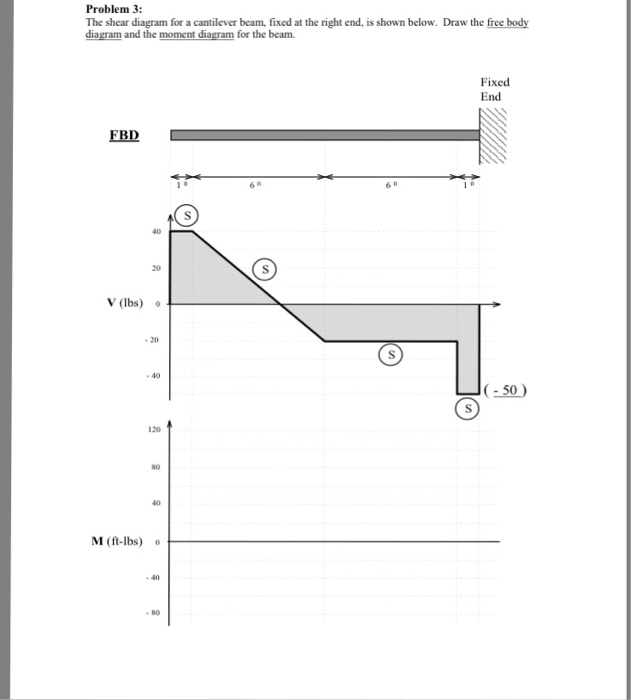
Solved Problem 3 The shear diagram for a cantilever beam ...
PDF Unit M4 - Massachusetts Institute of Technology Figure M4.3-7 Geometry and free body diagram of indeterminate beam main beam house walls concrete wall concrete lally wall columns ~ ~ ~ ~ ~ ~ ~ F F ~ ~ ~ ~ ~ FREE BODY DIAGRAM:--> We will save looking at the statically indeterminate case for a later unit. Let's start off by considering….

SHEAR FORCE AND BENDING MOMENT DIAGRAM FOR CANTILEVER BEAM ...
PDF BEAM DIAGRAMS AND FORMULAS - Arch Exam Academy beam diagrams and formulas by waterman 55 1. simple beam-uniformly distributed load 2. simple beam-load increasing uniformly to one end ... 22. cantilever beam-concentrated load at free end. 23. beam fixed at one end, free to deflect vertically but not rotate at other-concentrated load at deflected end 24. beam overhanging one support-uniformly ...

Cantilever beam under free-end force (loading, geometry and ...
Free Online Beam Calculator | SkyCiv Engineering Any changes made will automatically re-draw the free body diagram any simply supported or cantilever beam. The beam reaction calculator and Bending Moment Calculations will be run once the "Solve" button is hit and will automatically generate the Shear and Bending Moment Diagrams.

Solved) - Draw the free-body diagram for the cantilevered ...
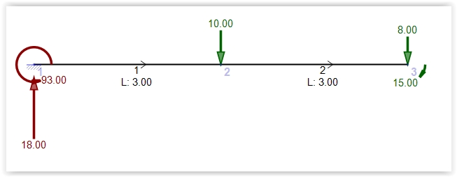
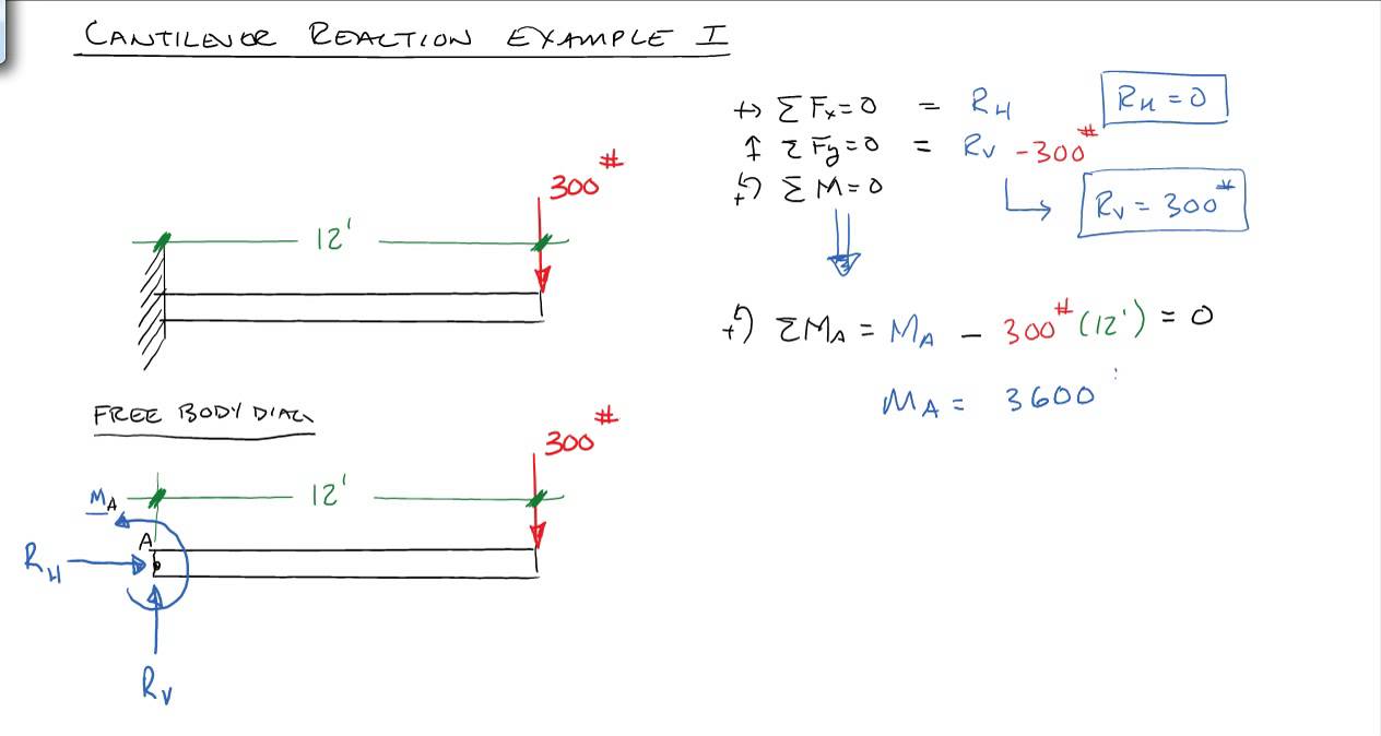
Lecture 23: Cantilever Free Body Diagram Example The video, then, displays a cantilever beam subjected to a point load of 20 N at free edge of the beam in downward direction. The length of the beam has given as 3 m. Next, using the given information, the video shows how to draw the FBD illustrating what reactions and momentum have been caused by the fixed support.

How to Draw a Free Body Diagram - Simply Supported Beam with a Point Load
Solved (a) Draw a free-body diagram of the cantilever beam ... Transcribed image text: (a) Draw a free-body diagram of the cantilever beam shown. (b) Determine the support reaction at the fixed end (point A). (c) Draw the shear and moment diagrams for the beam. (d) Determine the maximum shear force (absolute value), the largest positive bending moment, and the largest negative bending moment: and determine the locations on the beam where they occur.

The cantilever beam in Figure 3–29 is a steel American ...
A uniformly loaded propped cantilever beam and its free Strength Of Materials. Strength Of Materials Miscellaneous. A uniformly loaded propped cantilever beam and its free body diagram are shown below. The reactions are. R 1 =. 5qL. R 2 =. 3qL. ,M =.
Calculation Example – Cantilever Beam with point loads ...
Lecture 22: Simply Supported Beams Free Body Diagram ... Lecture Description. The objectives of this video are to give an introductory overview on how to use free body diagrams to deduce support reactions followed by a comprehensive workout on support reactions example. At first, the video illustrates a given diagram of simply supported beam having a pin support at left end and a roller support at ...

a) A cantilever under a concentrated load and (b) the free ...
Bending moment and shear force diagram of a cantilever beam In this article Learn :cantilever beam Bending moment diagram B.M.D. and shear force diagram S.F.D. of a cantilever beam having point load at the end,several point loads,U.D.L. Over Whole Span ,U.D.L. not over the whole span,U.D.L. from support to some distance,U.D.L. Somewhere on the beam,Combination of Point Loads and U.D.L.
How To Draw Shear Force And Bending Moment Diagram In Case Of ...
Timoshenko–Ehrenfest beam theory - Wikipedia The Timoshenko–Ehrenfest beam theory was developed by Stephen Timoshenko and Paul Ehrenfest early in the 20th century. The model takes into account shear deformation and rotational bending effects, making it suitable for describing the behaviour of thick beams, sandwich composite beams, or beams subject to high-frequency excitation when the …
A uniformly loaded propped cantilever beam and its free
PDF 3. BEAMS: STRAIN, STRESS, DEFLECTIONS The beam, or ... Cantilever beams and simple beams have two reactions (two forces or one force and a couple) and these reactions can be obtained from a free-body diagram of the beam by applying the equations of equilibrium. Such beams are said to be statically
Solving Reactions for a cantilevered beam
Everything You Should Know About Cantilever Beams - The ... Figure-3: Bending and Shear Force Diagram of Cantilever Beam with Point Load at Free End The shear force at the fixed support A is determined by keeping the section at A, which gives the shear force Ra=W; and moment Ma = W.l. based on which the shear force and bending moment diagram are developed.

SUBHANKAR 4 STUDENTS: S.F.D. for CANTILEVER BEAMS
6.2 Shear/Moment Diagrams – Engineering Mechanics: Statics Calculate the reactions using the equilibrium equations (may not need to do this if choosing a cantilever beam and using the free side for the FBD). Make a cut and add internal forces N V and M using the positive sign convention. Depending on the number of loads, you may need multiple cuts. Recall the positive convention: For shear, find an equation (expression) of the …
draw the free body diagram for the following problems a the cantilevered beam in prob 5 10 b the b 2
4.4: Relation Among Distributed Load, Shearing Force, and ...
Solved Problem 5.1 Vectors: FA ,Bx, By Part A Draw the ...

Bending moment and shear force diagram of a cantilever beam

The cantilever beam model with both a parallel and diagonal ...

Cantilever beam subjected to self-balanced moment and end ...

a) Cantilever beam model; (b) free-body diagram; (c) a ...
Cantilever beam bearing reactions • pickedshares
Solved Draw a free-body diagram of the cantilever beam and ...

Free Body Diagram of Cantilever Beam with Integrated F 2 MC ...

Figure A.1: Free body diagram of end-loaded cantilever beam ...
Solved Draw the free body diagram of the cantilever beam ...

Draw The Shear Diagram For Cantilever Beam | Beams, Bending ...

Cantilever beam Shear Force and Bending Moment diagram with Triangular load

HW16.11. Cantilever beam with distributed load Consider a ...

Solved) - For the cantilever beam shown below, draw the shear ...
Cantilever beam example where students need to complete the ...

Shear Force and Bending Moment diagram for cantilever beam ...

Shear Force and Bending Moment Diagram for Cantilever Beam ...
Beam Analysis - Validation | MechaniCalc
How To Draw Shear Force And Bending Moment Diagram In Case Of Cantilever Beam
0 Response to "41 cantilever beam free body diagram"
Post a Comment