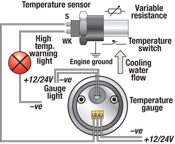
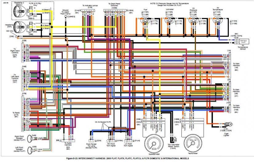
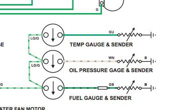
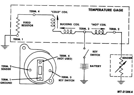
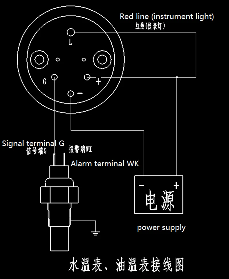
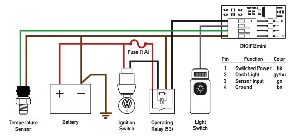
41 temperature gauge wiring diagram
Camry Electrical Wiring Diagram - Toyota Camry Repair 5.2.2022 · Internal wiring for each junction block is also provided for better understanding of connection within a junction block. Wiring related to each system is indicated in each system circuit by arrows (from_, to_). When overall connections are required, see the Overall Electrical Wiring Diagram at the end of this manual. Online Wiring Informa on - Home - Winnebago This will require use of the Wiring Iden fica on Guide. Delta note 4 makes reference to the manufacturer’s diagram for addi onal informa on. 3. For this example, we have iden fied wire “KA” that should have power but does not. Star ng at the connector at A‐3, follow the yellow 12‐gauge “KA” wire up and to the
Vdo Gauges Wiring Diagram Vdo Gauges Wiring Diagrams - Page 3 - Wiring Diagram And Schematics vdo marine fuel gauge wiring diagram best of gauge sending. Ford Fusion Relay And Fuse Box Diagram - List Of Schematic ford escape fuse box location just wiring data rh ag skiphire co uk. VDO Spin-Lok™ Clamp or mounting bracket 1 5.

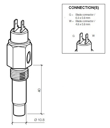
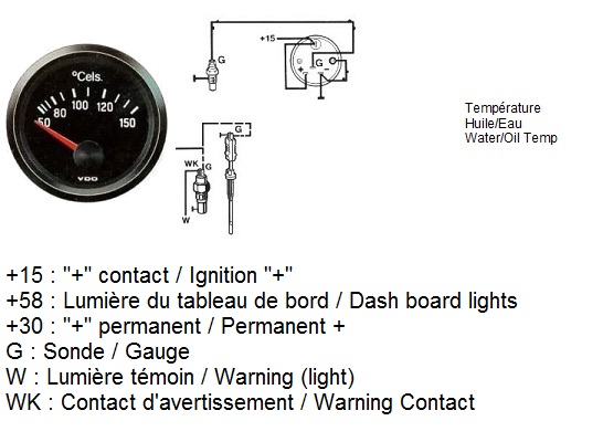
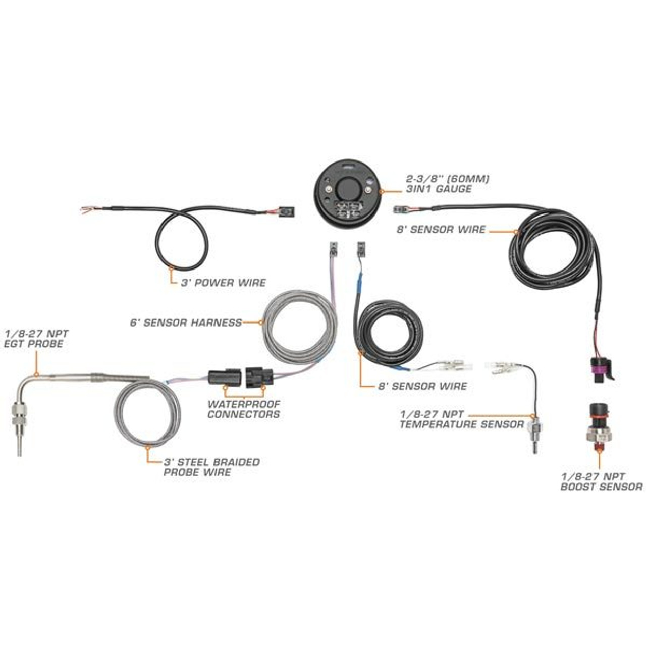
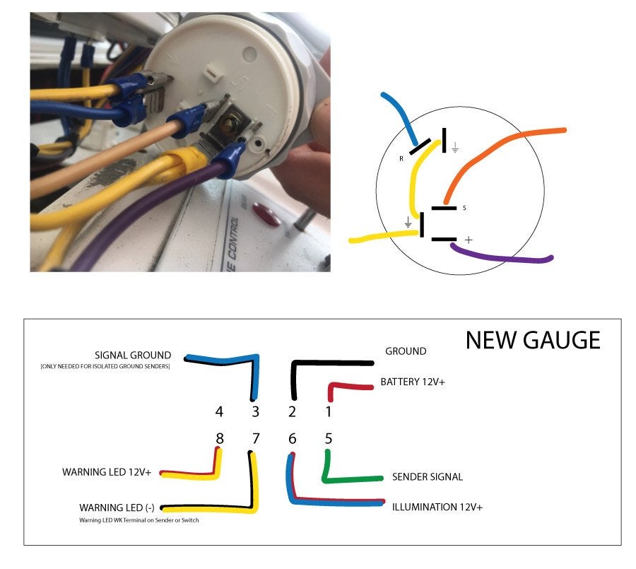
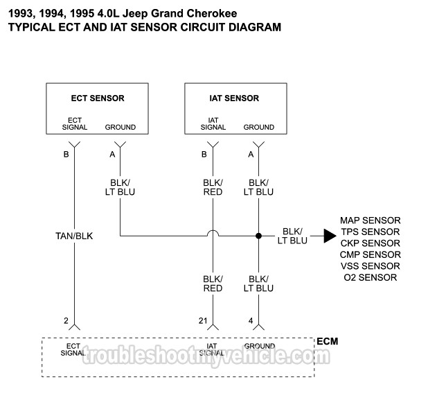
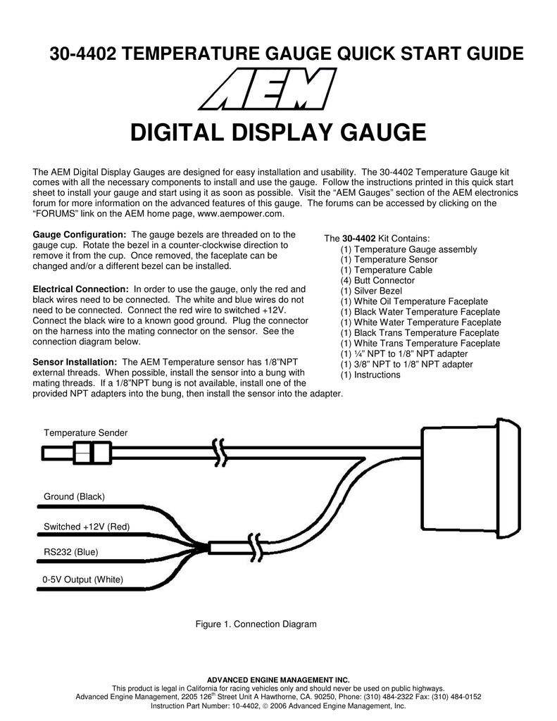
Temperature gauge wiring diagram
Autometer Gauge Wiring Diagram - Wiring Diagram Autometer Gauges Wiring Diagram Inspirational Wiring Diagram Auto - Autometer Gauge Wiring Diagram. Wiring Diagram consists of each illustrations and step-by-step directions that might allow you to definitely truly construct your project. This can be helpful for each the folks and for specialists who are looking to learn more on how to ... PDF 3.0 3.0 Installation Instructions Electrical Gauges/Kits ... TEMPERATURE GAUGE SWITCHED +12V (FUSE BOX) CHASSIS GROUND RED BLACK OPTIONAL GROMMET WASHER TERMINAL NUT LUG NUT ELECTRICAL TEMPERATURE SENDER ENGINE OPTIONAL BLOCK ADAPTER SENDER WIRE Figure 5. Electric Water Temperature Gauge Connections C. FUEL LEVEL GAUGE Fuel Level Gauges do not include a fuel level sending unit.These gauges are AUDI Fault Codes DTC - Car PDF Manual, Wiring Diagram ... Hello nice to meet you I got problem with my R300 BT (Radio), and need R300 BT wiring diagram for opel astra K 2017 sport tourer to repair it, can you plaeas send the diagram or pins info from R300 BT wiring diagram opel. Thnx ikramidis@hotmail.com #159. Ghaly (Saturday, 12 September 2020 16:36)
Temperature gauge wiring diagram. PDF 1969 Chevelle SS Gauge Conversion Diagram TEMPERATURE GAUGE 1. Locate the original dark green wire found at location T-C in the fuse block bulkhead connector as shown on page 4 and remove it from the connector. Plug the loose terminal on the dark green wire (35A on page 3) from the Dash Side Gauge Harness Extension into the fuse block bulkhead connector at location T-C as shown on page 4. Boat Fuel Gauge Wiring Diagram - easywiring Boat fuel gauge wiring diagram. Fuel systems marine voltage i to g terminal 10 to 16 volts. Saved by michael appiah. Install the new gauge reconnect the wiring and turn on the power. 800 x 600 px source. To test senders the resistance values are shown at minimum and full gauge scales. How to install a moeller fuel gauge. 472 WIRING DIAGRAMS - Discount Marine WIRING DIAGRAMS 473 13 Diagram Key Connectors Ground Frame ground No connection Connection Starter relay Electric starter Battery ... warning gauge ECU 225 HP MODELS. WIRING DIAGRAMS 477 13 Diagram Key Connectors Ground Frame ground ... Temperature gauge Trim position gauge Harness connector for Instruments & remote control (to engine) … PDF Bosch Custom Gauges Installation Instructions - CARiD.com the positive side (Diagram 2A) of the lighting circuit: Diagram 2A Connect the black wire into the circuit between the dimmer control and the dash lights. Con - nect the red wire to the fuse box so that the wire only receives +12-volt power when the dash lights are turned on. GAUGE DASHBOARD BRACKET NUTS & WASHERS TOP VIEW Diagram 1 Diagram 2B ...
Temperature Gauge Wiring Diagram For Your Needs Temperature Gauge Wiring Diagram. Print the electrical wiring diagram off in addition to use highlighters to trace the routine. When you use your finger or even stick to the circuit along with your eyes, it may be easy to mistrace the circuit. A single trick that I use is to printing the same wiring diagram off twice. 4 Reasons Why Your Gas Gauge Isn't Working - LiveAbout 24.5.2018 · Gas gauge test. When testing at the gas gauge, repeat the voltage check from the sending unit. The voltage should be exactly the same as when you tested at the sending unit. If the voltage is different, you likely have corrosion or … Temperature Gauge Wiring Diagram | Electrical diagram ... Temperature Gauge Wiring Diagram. Temperature Gauge Wiring Diagram. frans. 4 followers . Electrical Switch Wiring. Light Switch Wiring ... Detailed coloured12N Trailer Wiring Diagram which is commonly used on UK and european trailers and caravans from Western Towing. T. Tim. Trailer wiring diagram. Engine Repair. Vdo Water Temp Gauge Wiring Diagram - schematron.org diagram g wiring diagram wiring of power and ground to each gauge illumination wiring and wiring of senders to each gauge. Find VDO Gauges Gauges, Analog with Water temperature Gauge Type and get Free Shipping on Orders Over $49 at Summit Racing!
How to Wire a Temperature Gauge - It Still Runs A vehicle owner can wire a temperature gauge in his or her vehicle in a driveway or garage. Step 1. Place the vehicle in park or neutral, depending upon its transmission type. Set the emergency brake. Raise the hood and disconnect the negative battery cable with a socket. Refer to your owner's manual for the location of your existing ... Vdo Water Temp Gauge Wiring Diagram Diagram E. the sender body, or backwards, the fuel gauge will read "FULL" when the temperature sender Refer to the wiring diagram, Diagram G. Wire gauges in series from a positive (+) Temperature: Needle to the temperature of the engine water.Using the expertise we've gained in developing specialized solutions for many of the world's ... Smiths Water Temperature Gauge Wiring Diagram Smiths gauges made after 1964 have two terminals. Wiring diagram for smiths classic gauges a coupe of guys were discussing the wiring of ammeters on the yahoo. The side with only 1 plug fitted a voltage regulator ts7810cz 1a positive fixed voltage regulator to220 case from maplin. Triumph herald group so ive dug out this wiring diagram that ... Autometer Trans Temp Gauge Wiring Diagram Trans Temp Gauge Installation: but an A-pillar gauge mount is available as a professional location to mount two gauges. diagramweb.net has a 2 & 3 gauge pod available Pictured below is a copy of the wiring diagram for the Autometer Transmission Temperature Gauge. STEP 4.
PDF Viewline Instrument Kit Installation Instructions Tech ... making alterations to wire harness. The included harness's black ... 250F Temperature gauge (1) 80 PSI oil pressure gauge (1) E-F fuel gauge ... deviate from assembly or wiring diagram. Always disconnect battery ground before making any electrical connections. IMPORTANT: ...
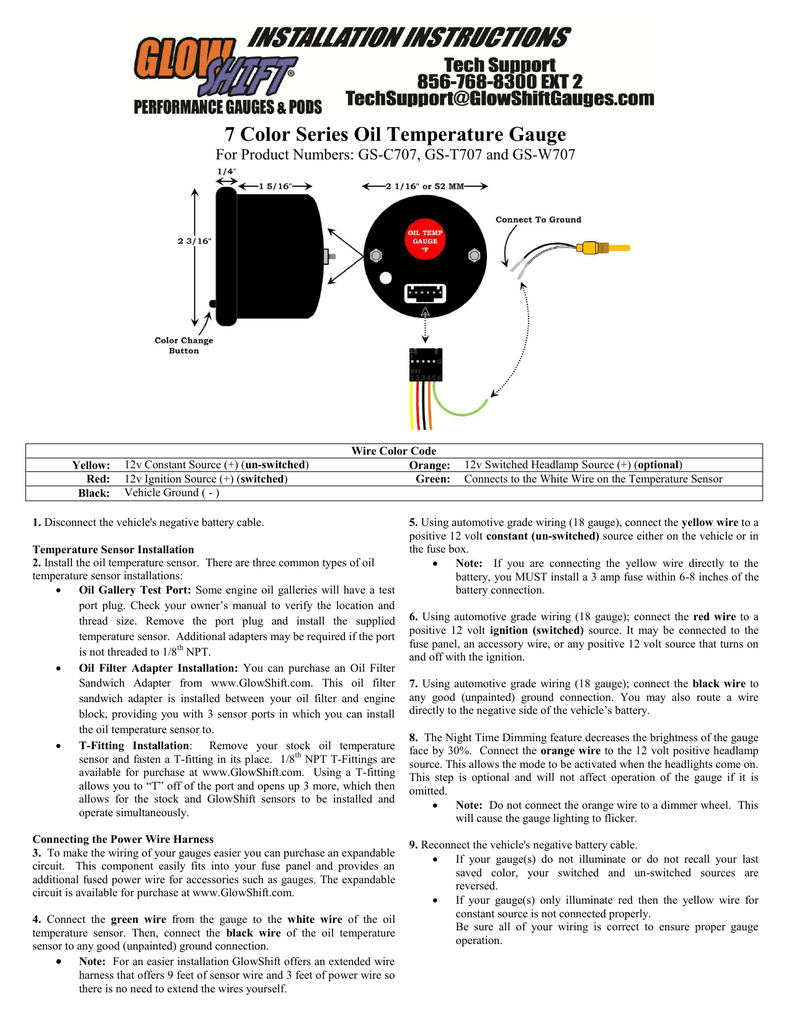
Glowshift Volt Gauge Wiring Diagram - U Wiring Rpm gauge wiring diagram. Glowshift 7 Color Series Transmission Temperature Gauge User Manual 3 Pages Also For Transmission Temperature Gauge . Our battery cable is American made and comes in gauge AWG sizes of 6 4 2 1 10 20 30 and 40 with 6 gauge being the smallest and 40 gauge being the largest.
AUDI - Car PDF Manual, Wiring Diagram & Fault Codes DTC AUDI Car Owner Manuals & Service Manuals PDF above the page - 80, 100, 200, Allroad Quattro, A3, S3, A4, A5, A6, R8, RS2, RS4. Q5, Q7, SQ5; AUDI Fault Codes DTC, Wiring Diagrams.. Audi - one of the most recognizable in the world of automobile brands. Today, this German company belongs to the car concern Volkswagen.. Automobile plant Audi Automobil …
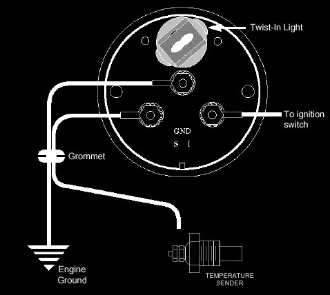
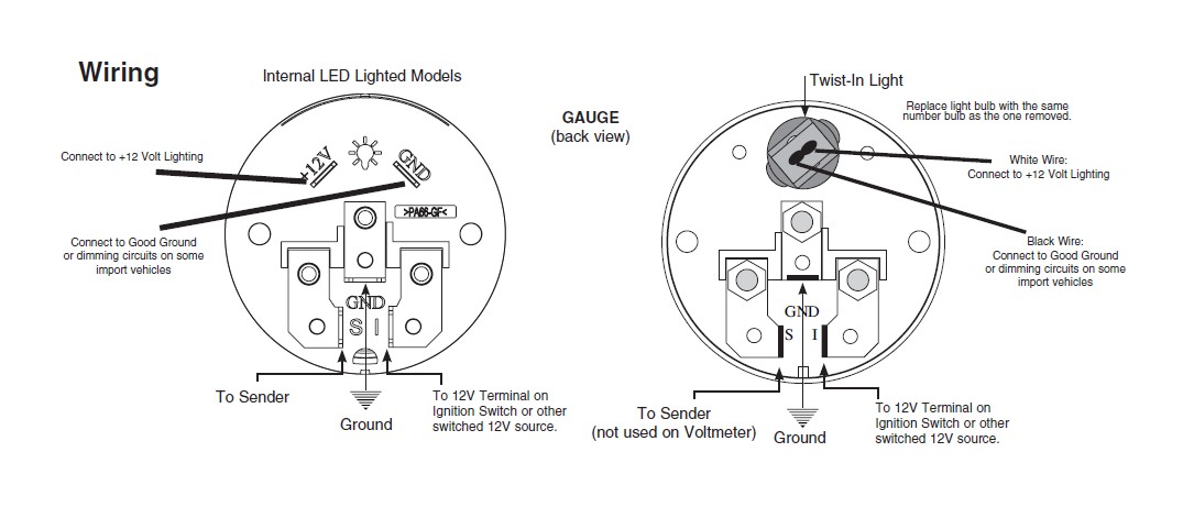
PDF 1957 Chevy Installation Manual Revision 010615 Temperature Gauge Wiring 1) Always disconnect the vehicle battery before wiring any gauge. 2) Connect a switched +12VDC power source to the post marked "I" on the back of the temperature gauge. 3) Connect a good chassis ground to the post marked "G" on the back of the temperature gauge.
PDF UNIVERSAL WIRING HARNESS - Wiring Wizard Tan Gas sender wire Connect to the 'SENDER' location on gauge. White Tach sender wire Connect to the 'SENDER' location on gauge. (-) Black Ground Connect to each gauge (ground location) as shown in diagram. Pink 12 volt ignition feed Connect to each gauge (12 v location) as shown in diagram.
Vdo Gauges Wiring Diagram - schematron.org Description: Vdo Gauges Wiring Diagrams And Boat Tach Diagram E Z Go Golf Cart for Boat Gauge Wiring Diagram For Tachometer, image size X px, and to view image details please click the image. Here is a picture gallery about Boat Gauge Wiring Diagram For Tachometer complete with the description of the image, please find the image you need.
SUZUKI - Motorcycles Manual Pdf, Wiring Diagram & Fault … 2.3.2022 · Need wiring diagram for 1997 Honda Goldwing Gas gauge, temperature gauge, reverse and back running lights not working #560 Alberto ( Thursday, 23 September 2021 22:52 )
Wheatstone Bridge - Load Cell Manufacture One active strain-gauge element and one passive, temperature-sensing quarter-bridge element (dummy gauge). The active element is mounted in the direction of axial or bending strain. The dummy gauge is mounted in close thermal contact with the strain specimen but not bonded to the specimen, and is usually mounted transverse (perpendicular) to the principle axis of strain.
General Motors temperature gauge troubleshooting ... Temperature gauge troubleshooting begins with isolating the problem either to the gauge, sending unit, fuse or wiring. As with any electrical troubleshooting it is best to check all wiring connections are clean, tight and free of corrosion. The following process must be preformed with the ignition key turned to the "on" position.
PDF HELP?: GENERAL APPLICATION: Installation Instructions ... TEMPERATURE GAUGE WIRING (Figure 3): 1. Disconnect negative (-) battery cable. 2. Using 18-ga. wire, connect the (G) terminal to a clean (rust/paint-free) ground surface near the temperature sender. 3. Using 18-ga. wire, connect the (I) terminal to a switched +12V source. 4. Using 18-ga. wire, connect the (S) sender terminal of the
Wiring Diagrams - Classic Instruments Wiring Diagrams. 01 Six Gauge Set Wiring Diagram 11/10/09. 01 Six Gauge Set Wiring Diagram 5/9/19. Six Gauge Set Wiring Diagram SNWH03 . All-American 3200/6400 Package Guide Rev 2/27/13. Download 3200 Wiring Instructions Rev 2/7/13. Download 6400 Wiring Instructions Rev 2/7/13 . Senders . SN11 Low Volt Light Rev 7/12/12
Temperature Gauge Wiring Diagram | autocardesign Temperature Gauge Wiring Diagram - wiring diagram is a simplified all right pictorial representation of an electrical circuit. It shows the components of the circuit as simplified shapes, and the aptitude and signal associates amid the devices.
Vdo Water Temperature Gauge Wiring Diagram - Wiring Diagram Vdo water temperature gauge wiring diagram. I installed the vdo oil pressure and temperature gauges in my 1970 vw but will give you the concept on installing them in any vehicle. Coolant temperature oil temperature oil pressure fuel level and speed. All in one digital display system. This is part 1 on how to install vdo gauges.
Vdo Volt Gauge Wiring Diagram - easywiring Black 7 Color Celsius Oil Temperature Gauge Air Pressure Gauge Fuel Pressure Gauge Gauge Kit . Tachometer Wiring Diagrams Car Gauges Diagram Gauges . Pin On Automotive Lighting And Electrical . Pin On Products . Sponsored Ebay 52mm White Green Maxtow 250 F Differential Temperature Gauge Mt Wdv22 Diesel Trucks Fuel Pressure Gauge Gauges
Gauge Wiring Diagrams - ETB Instruments 80 & 100mm Electronic Speedometer Mk3 - General Wiring Diagram & Instructions, Hall-effect M8 sensor (340 002) + Magnetic Induction Sensors. 433kb. 80 & 100mm Electronic Speedometer Mk3 - Hall-effect Gear Tooth Sensor (340 017) + Speedometer Disc / Bolt Heads. 366Kb. 80 & 100mm Electronic Speedometer Mk3 - Rover SD1 Sensor.
Thermostat Wiring Diagrams Quality HVAC Guides 101 That is a basic Honeywell thermostat wiring diagram for a single-stage heat pump. If you have a two-stage heat pump, then you will also utilize terminal Y2 for the second stage. Furthermore, this thermostat wiring diagram is specifically for a system with two transformers.Your system likely only has one transformer, as most typical residential systems only use a single transformer for …
Temperature Gauge Wiring Diagram - Ford Mustang Forum Temperature Gauge Wiring Diagram. Jump to Latest Follow 1 - 3 of 3 Posts. H. hack67 · Registered. Joined Nov 17, 2009 · 9 Posts . Discussion Starter · #1 · Dec 31, 2009. I recently bought a 1967 Mustang Coupe 289 2V. ...
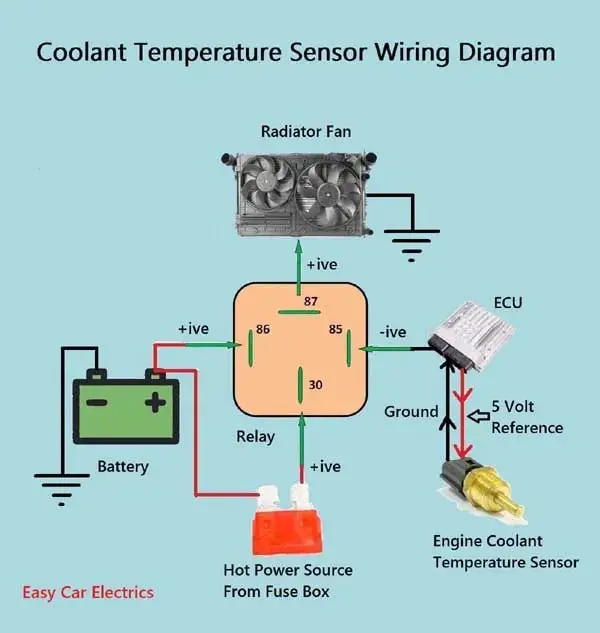
1, 2, & 3 Wire Coolant Temperature Sensor Wiring Diagram 3 Wire Coolant Temperature Sensor Wiring Diagram The two wires, a "5-volt reference", and a "ground wire" go to the ECU, and the third wire "Earth Signal Wire for Temperature Gauge" goes to the cluster-mounted temperature gauge by providing an earth signal to the temperature gauge.
Autometer Water Temp Gauge Wiring Diagram Aug 15, · Autometer Pyrometer Wiring Diagram auto meter ficial site trade in any aftermarket gauges for credit on new autometer gauges 15 trade in trade up read more auto Autometer Pyrometer Wiring Diagram Isspro Electric Water Temp img source: diagramweb.net Autometer Pyrometer Wiring Diagram As Well As Temperature Gauge img source.
Camper Van Electrical Design with Detailed Wiring Diagram 5.11.2021 · The diagram above outlines in the most simplistic terms, my camper van electrical design. Using the formula explained here, I calculated I’d need about 80 amp hours (ah) per day including contingency. Assuming the batteries are 50% efficient, I’d need to fit 160ah batteries.
1969 Camaro Console Gauge Wiring Diagram - My Wiring Info 1968 Camaro Wiring Diagram - Collections Of 1969 Camaro Console Diagram Line Schematic Diagram •. Gray from gauge illumination circuit (gauges fuse) to illuminate the shift quadrant. 91 f350 7.3 alternator wiring diagram regulator Which direction the resistors are laid and also the long black wire on the harness. 1969 camaro console gauge wiring diagram. […]
AUDI Fault Codes DTC - Car PDF Manual, Wiring Diagram ... Hello nice to meet you I got problem with my R300 BT (Radio), and need R300 BT wiring diagram for opel astra K 2017 sport tourer to repair it, can you plaeas send the diagram or pins info from R300 BT wiring diagram opel. Thnx ikramidis@hotmail.com #159. Ghaly (Saturday, 12 September 2020 16:36)
PDF 3.0 3.0 Installation Instructions Electrical Gauges/Kits ... TEMPERATURE GAUGE SWITCHED +12V (FUSE BOX) CHASSIS GROUND RED BLACK OPTIONAL GROMMET WASHER TERMINAL NUT LUG NUT ELECTRICAL TEMPERATURE SENDER ENGINE OPTIONAL BLOCK ADAPTER SENDER WIRE Figure 5. Electric Water Temperature Gauge Connections C. FUEL LEVEL GAUGE Fuel Level Gauges do not include a fuel level sending unit.These gauges are
Autometer Gauge Wiring Diagram - Wiring Diagram Autometer Gauges Wiring Diagram Inspirational Wiring Diagram Auto - Autometer Gauge Wiring Diagram. Wiring Diagram consists of each illustrations and step-by-step directions that might allow you to definitely truly construct your project. This can be helpful for each the folks and for specialists who are looking to learn more on how to ...









0 Response to "41 temperature gauge wiring diagram"
Post a Comment