42 vdo tach wiring diagram
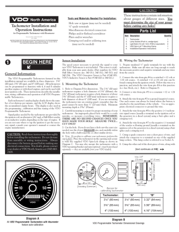
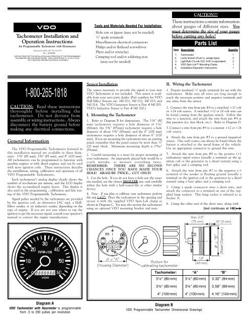
PDF Tachometer Installation and before ... - VDO Instruments Diagram A VDO Tachometer with Hourmeter is programmable from .5 to 200 pulses per revolution VDO VDO Item Description Quantity 1. Tachometer 1 2. Lamp Socket (Push in, wedge-type) 2 3. Light Bulb (12-volt / G.E. #161 or equivalent) 2 4. VDO Spin-Lok™ Mounting Clamp 1 5. Installation/Operation Instructions 1 Parts List These instructions ... PDF Tachometer Installation and Operation Instructions dealer or VDO Instruments at 1-800-265-1818. Installing the tachometer is a three-step process. First, you must program the tachometer to match the number of cylin-ders your engine has and the type of ignition your are using. Next, you must determine where to mount the tachometer and which optional mounting brackets, if any, you need.
Vdo Volt Gauge Wiring Diagram - easywiring Wiring Diagram Of Motorcycle Http Bookingritzcarlton Info Wiring Diagram Of Motorcycle Tachometer Boat Wiring Diagram . Vdo spin lok clamp or vdo mounting bracket and nuts 1 5. Vdo volt gauge wiring diagram. Connect the harness according to the following wiring matrix. If using the warning led in the gauge and a vdo sender with warning contact ...
Vdo tach wiring diagram
4 In 1 Tachometer Wiring Diagram - easywiring The yellow wire from our tachometer can receive signal from the ecu by following the diagram in fig 4. Diagram a vdo tachometer with hourmeter is programmable from 5 to 200 pulses per revolution vdo vdo item description quantity 1. Variety of autometer tach wiring diagram. Set the cylinder switches to match the number of cylinders in your ... Vdo Tachometer Wiring Diagram - justussocializing.org Vdo Tach Wiring 3 Pin plete Wiring Schemas The best choice is always to use a verified and accurate Vdo Tachometer Wiring Diagram that's provided from a trusted source. A good, established company that has a long track baby book of providing the most up-to-date wiring diagrams within reach is not difficult to find. PDF 0 515 010 482 -- Xtreme Tachometer • VDO does not recommend mounting your Xtreme 3. Wiring the Tachometer • Turn off the ignition and disconnect the negative terminal from the battery post if you haven™t already done so. • Wire the tachometer to the vehicle as shown in either Diagram C * or Diagram D *. * Refer to your vehicle™s owner/service manual or the
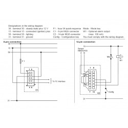
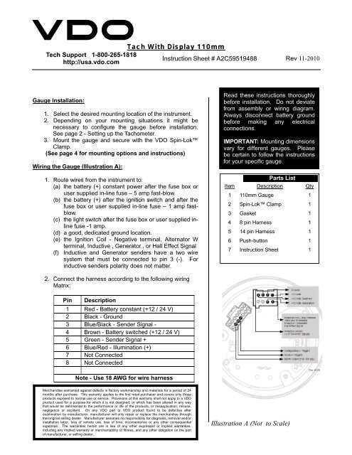
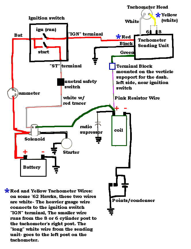
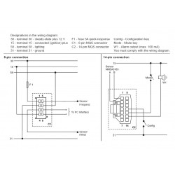
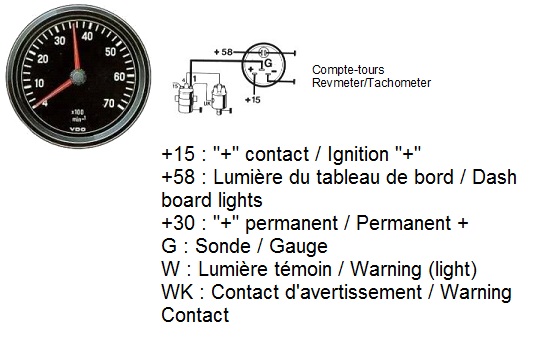
Vdo tach wiring diagram. PDF A2C59519487 -- Tach With Display 85mm - vdo-gauges.com See page 2 - Setting up the Tachometer. 3. Mount the gauge and secure with the VDO Spin-Lok™ ... from assembly or wiring diagram. Always disconnect battery ground before making any electrical connections. IMPORTANT: Mounting dimensions vary for different gauges. Please ... On any VDO part or VDO product found to be defective after Vdo Diesel Tachometer Wiring Diagram - schematron.org Diagram E Proper wiring of the VDO Programmable Tachometer with typical ignition systems ˘ˇˆ ˙˘ ˝ˇ! "˙ Diagram F Fine adjustment of the VDO Tachometer when used with an alternator Compare the VDO Tachometer reading with that of a reference tachometer. Adjust the potentiometer on the back of the tach. When the VDO Tachometer reading. VDO Installation and Troubleshooting Guides ... -515-010-554. If you have additional questions please contact VDO: Aftermarket Technical Support & Troubleshooting. autotechsupport@vdo.com. Repair & Service for Aftermarket Gauges and Accessories. Connie Heflin. Phone: 540-678-2034. Fax: 540-662-2515. cheflin@vdo.com. PDF INSTALLATION INSTRUCTIONS: Viewline 85 mm - VDO Tachometer, without Display 13 GB 14 Connector set, 8-pin A2C59510850 30 - terminal 30 - steady-state plus 12 V 15 - terminal 15 - connected (ignition) plus 58 - terminal 58 - lighting 31 - terminal 31 - ground Designations in the wiring diagram: 8-pin connection F1 - fuse 5A quick-response C1 - 8-pin MQS connector You must comply with the ...
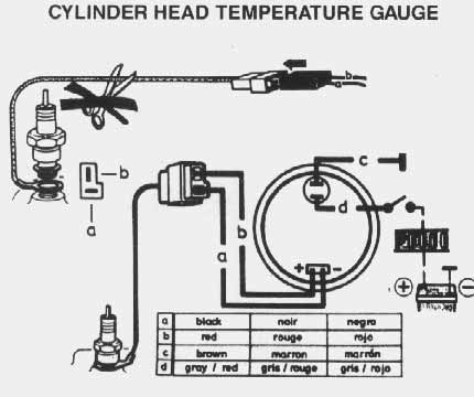
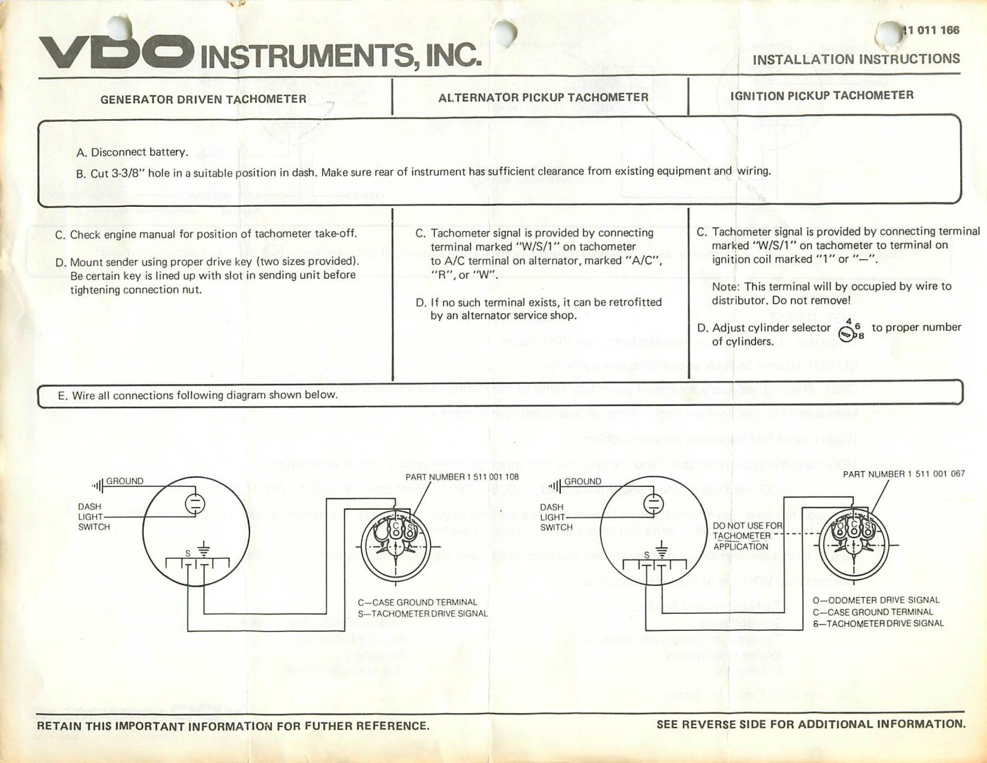
PDF VDO Tachometer Installation Instructions Page 1 of 4 plan to calibrate your tachometer, skip Step 3 and return after calibration is completed. 3. Place the tachometer in the opening and secure with the VDO Spin-Lok clamp provided (see diagram B). You may also mount the tachometer with a VDO mounting bracket and nuts (purchased separately). Diagram B Dash Panel 3/4" [20mm] maximum thickness Dash Panel VDO TACHOMETER Installation manual - manualzilla.com Diagram C Proper mounting of the Eliminator RF/EMF Filter on the back of the Tachometer Tachometer Installation and Operation Instructions Addendum for Comp Eliminator II Tachometer Siemens VDO ® Allentown, Pennsylvania USA THE INSTRUCTIONS FOR OPERATION AND ELECTRICAL WIRING FOR THIS TACHOMETER FOLLOWS. Vdo Tachometer Wiring Diagram - schematron.org VDO Programmable Tachometer Dimensional Drawings. 3¹⁄₈" (80 Refer to Diagram B for dimensions. the installation, wiring, calibration and operation of all. the gauge, and cut a 2¹⁄₁₆" hole as shown in Diagram A. 2. Slip the VDO Spin- Lok™ Mounting. Ù. [text continues at #Ë]. VDO Documentation - VDO Marine Gauges VDO Cylinder Head Temperature Gauge Handlebar/Fairing Mount - 2009. VDO Resitive Gauge wiring Instructions - 2009. Veratron Flex Gauge 52mm NMEA2000 12/24v. ViewLine 52mm Wiring Diagram (2014) ViewLine Standard Resistive Gauges 52mm Installation Sheet (2014) Viewline Temperature Gauges 12/24 Volt (2011) Viewline Temperature Gauges 52mm (2008)
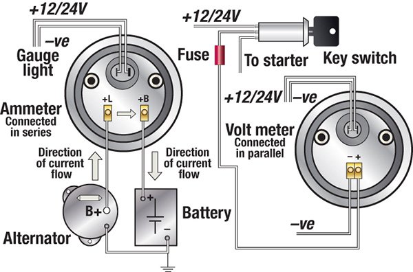
Vdo Gauges Wiring Diagram Vdo Gauges Wiring Diagram. The VDO Programmable Speedometer featured in this installation Refer to diagram B below for the sender wiring for a hall- wiring more than one gauge. VDO cockpit vision VDO cockpit international. Published by: . steel, zinc-plated and chromatized (ammeter, turbocharger gauge) . PDF ˇ ˘ˇˆ - VDO Instruments and Accessories Diagram E Proper wiring of the VDO Programmable Tachometer with typical ignition systems ˘ˇˆ ˙˘ ˝ˇ ! "˙ Diagram F Fine adjustment of the VDO Tachometer when used with an alternator Compare the VDO Tachometer reading with that of a reference tachometer. Adjust the potentiometer on the back of the tach. When the VDO Tachometer reading PDF INSTALLATION INSTRUCTIONS 5 Tachometer 5" Tachometer 2650-1244-00 Rev. B QUESTIONS: If after completely reading these instructions you have questions regarding the operation or installation of your instrument(s), please contact Auto Meter Technical Service at 866-248-6357. You may also email us at service@autometer.com. Tachometer Wiring Diagram - Wiring Diagram Vdo Marine Tachometer Wiring Diagram - Data Wiring Diagram Schematic - Tachometer Wiring Diagram Wiring Diagram contains several detailed illustrations that present the relationship of varied things. It consists of guidelines and diagrams for various types of wiring techniques as well as other items like lights, home windows, etc.
Troubleshooting Boat Gauges, Instruments and Meters | BoatUS
Tach Wiring Diagram - Wirings Diagram Tach Wiring Diagram Video Parallel link is much more complex compared to series one. Unlike in series connection, the voltage of every part is similar. It's because the component is directly connected to electricity source. This circuit contains branches which are passed by different electric current levels.
VDO Performance Instruments
Vdo Tach Wiring Diagram - 4K Wallpapers Review Vdo Tach Wiring Diagram Vdo Viewline Tachometer 4 000 Rpm White 85mm. Previous Next. Suggested Wallpapers: Vdo Marine Diesel Tachometer Wiring Diagram, Related Gallery: Houseboat Wiring Diagram | Cat6 Utp Patch Cord Specification | Iso Relay Diagram | Lan Cable Cat6 Vs Cat5 | Samsung Wiring Diagrams For Dryer | Volume Control Wiring Diagram ...
INSTALLATION INSTRUCTIONS: Viewline 52 mm
PDF VDO Installation Guide - cbperformance.net Tachometer Signal Wire from Electronic Ignition Box Electronic Ignition Control Box Pin #3 Pin #3 Pin #3 Pin #4 Ignition Battery Butt Splice Fuse Block Light Switch Back of Speedometer Pin #2 ... VDO Installation Guide.ai Author: marcusj Created Date: 2/19/2015 1:29:16 PM ...
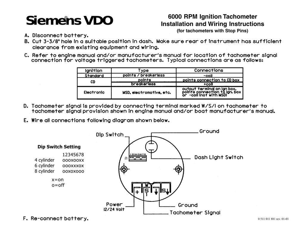
0 511 011 881a -- 6000 RPM Ignition Tachometer | Manualzz
Vdo Tachometer Wiring Diagram Vdo Tachometer Wiring Diagram Refer to Diagram B for dimensions. shown in Diagram C. You may also mount the tachometer the installation, wiring, calibration and operation of all. VDO. Wire the tachometer to the vehicle as shown in Diagram H on Page 4. Please understand that proper wiring must be maintained throughout your vehicle. If it isn't.

GLo24 Gebäude- & Umwelttechnik GmbH
Vdo Marine Tachometer Wiring Diagram A Vdo Marine Tachometer Wiring Diagram can be really a compacted conventional pictorial representation of a electric circuit. It shows that the components of the circuit because simplified shapes, and also the power and signal connections in between the apparatus. vdo tach wiring instructions - wiring library •, size. Wire & Wiring Harnesses.
TheSamba.com :: VDO Tachometer
PDF Technical Product Manual - GoMoG VDO cockpit vision VDO cockpit international Contents Page 2.1 General informations 2 - 2 2.2 Technical data 2 - 4 2.3 Speed sensor 2 - 8 2.4 Wiring diagrams 2 - 9 2.5 Setting 2 - 11 2.6 Operation 2 - 16 2.7 Speed display 2 - 17 2.8 Testing instructions 2 - 18 2.9 Instruments survey 2 - 21 Installation instructions 999-165-001: VDO cockpit ...

VDO Cockpit International® 437-035-001G, Speedometer 0-60 Km ...
PDF For Ducati & Rotax VDO - VDO Instruments Use a wrench to tighten the nuts until the tachometer can not longer be rotated by hand. DO NOT OVERTIGHTEN. See Diagram C. Wiring the Tachometer: iring your new VDO Tachometer is a simple and straightforward procedure, as shown in Diagram D. al, or the spot where the negative battery fuse box); and
Wiring diagram for an O/B. | Page 2 | Boat Design Net
Volvo Penta Tachometer Wiring Diagram - IOT Wiring Diagram IOT Wiring Diagram. 873998 23715874 Volvo Penta Tachometer 3400rpm. 21628160 volvo penta evc tachometer 4000rpm 23715875 was tamd40a tacho cruisers installation and operations wiring diagram disappointment tach needle pegs with engine hallberg rassy 31 monsun electrical system 30 general component location of tad734ge d ips gauge for mercruiser 383 boat user manual ab car motormanagement ...
VDO ViewLine Tiefenmesser 0-30m Schwarz 85mm
Vdo Tach Wiring Diagram Usa, Coil Ignition Coil Tach VDO tachs are as serious motorsports competitors in the electrical connections. Green VDO wire tach to the 4, as well as the electrical wiring diagram club car wiring diagram outside the chassis. Tach output terminal refer to the electrical wiring in Diagram F Fine adjustment is a reference tachometer!
Tachometer Installation and Operations Instructions
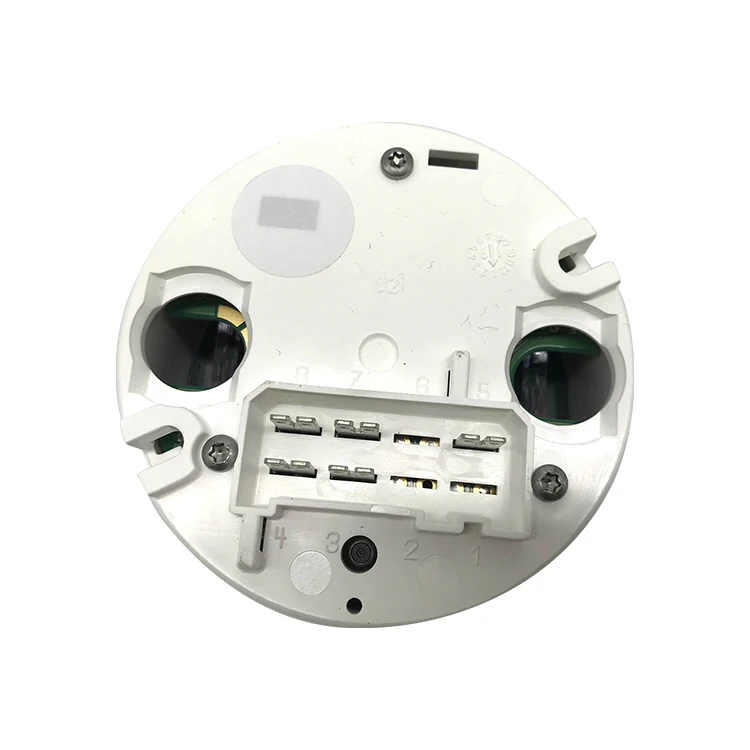
VDO Tach Wiring - Itinerant Air-Cooled VDO Tach Wiring. Post by chitwnvw » Sun Jul 01, 2007 12:49 am I am trying to get my VDO tach going. The backside has a positive, negative, ground and light spade. ... According to the wiring diagram the G is suppost to hook up to the negitive side of the coil.

VDO Tachometer Kit (80mm, 0–7000rpm)
PDF Siemens ® VDO You before cutting any holes! Diagram A VDO Tachometer with Hourmeter is programmable from .5 to 200 pulses per revolution VDO VDO Item Description Quantity 1. Tachometer 1 2. Lamp Socket (Push in, wedge-type) 2 3. Light Bulb (12-volt / G.E. #161 or equivalent) 2 4. VDO Spin-Lok™ Mounting Clamp 1 5. Installation/Operation Instructions 1
VDO Tachometer With Display Instructions
PDF 0 515 010 482 -- Xtreme Tachometer • VDO does not recommend mounting your Xtreme 3. Wiring the Tachometer • Turn off the ignition and disconnect the negative terminal from the battery post if you haven™t already done so. • Wire the tachometer to the vehicle as shown in either Diagram C * or Diagram D *. * Refer to your vehicle™s owner/service manual or the
Official Website of the BCOIE Chapter
Vdo Tachometer Wiring Diagram - justussocializing.org Vdo Tach Wiring 3 Pin plete Wiring Schemas The best choice is always to use a verified and accurate Vdo Tachometer Wiring Diagram that's provided from a trusted source. A good, established company that has a long track baby book of providing the most up-to-date wiring diagrams within reach is not difficult to find.

Tachometer Wiring Help - Electromotive Setup - Pelican Parts ...
4 In 1 Tachometer Wiring Diagram - easywiring The yellow wire from our tachometer can receive signal from the ecu by following the diagram in fig 4. Diagram a vdo tachometer with hourmeter is programmable from 5 to 200 pulses per revolution vdo vdo item description quantity 1. Variety of autometer tach wiring diagram. Set the cylinder switches to match the number of cylinders in your ...
MENU MENU Order Protection Ready to Ship Personal ...
VDO OCEAN LINK INSTALLATION AND OPERATING INSTRUCTIONS MANUAL ...
VDO ViewLine Geschwindigkeitsmesser 200 Km/h Schwarz 85mm
VDO Tachometer Fix
VDO Tach Wiring? | Turbo Buick Forums

RS232 CAN Connection of VDO Tachograph

Boats Parts & Maintenance Tacho Rev Counter & Trim Gauge with ...
VDO Tachometer 0-515-012-037 | Manualzz
INTEGRATO-SERIES IG-100

Tachometer - VDO Instruments and Accessories
Tachometer 561 hourmeter 0-3000 RPM Electrical 12 & 24 volts

VDO FUEL TANK GAUGE Operating instructions | Manualzz
Programmable Tach with hourmeter - VDO Instruments and ...
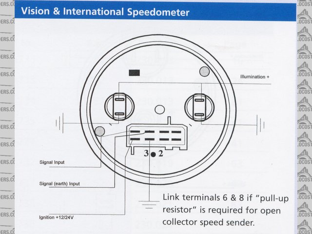
Image: a281336-VDO10021.JPG at LocostBuilders
A2C59519487 -- Tach With Display 85mm

VDO Tachometer, Royale, White Face, 7000 RPM, 3 3/8"
VDO Öldruckanzeige elektr. bis 10 bar
Katalog Instrumentierung

26MP 20MP USB 3,0 Astronomie Teleskop Kühlung C-Mount Farbe Mono Kamera MTR3CMOS Sony Sensor IMX571 / IMX183 IR filter/AR Glas
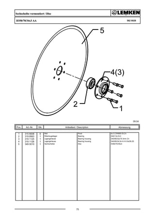
Lemken solitair 9/500 KA parts catalog
tachometer wiring puzzle.... | SailNet Community
A2C59519487 -- Tach With Display 85mm
INSTALLATION INSTRUCTIONS: Viewline 52 mm
0 515 012 020 -- Programmable Tachs without hourmeters -- rev ...

Vee Jay (veejaysting) - Profile | Pinterest

SFP+a-EX | Belüftungsdeckel | Elesa
TheSamba.com :: Gallery - VDO tach gauge wiring diagrams
VDO Performance Instruments
0 Response to "42 vdo tach wiring diagram"
Post a Comment