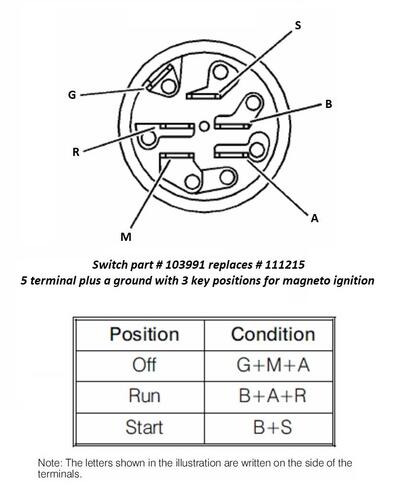
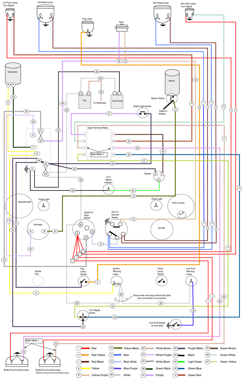
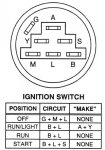
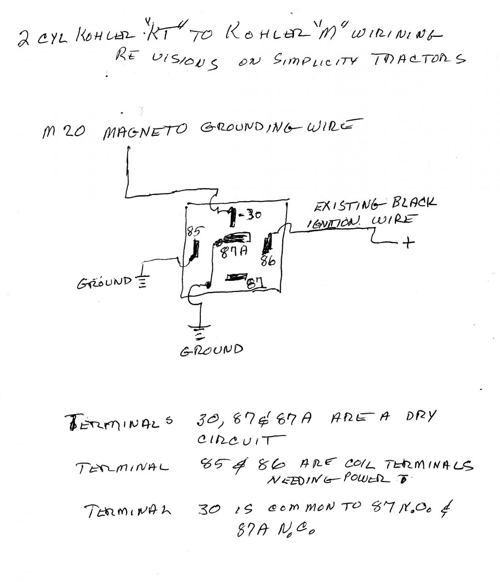
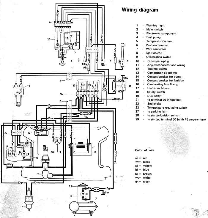
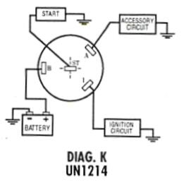
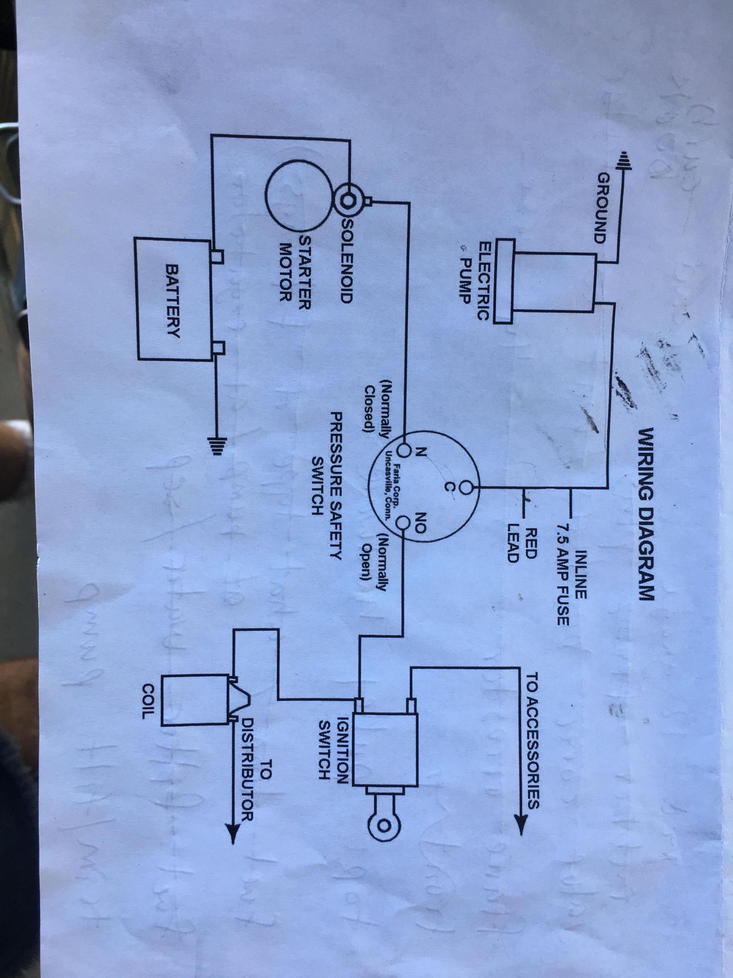
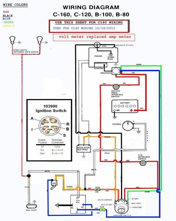
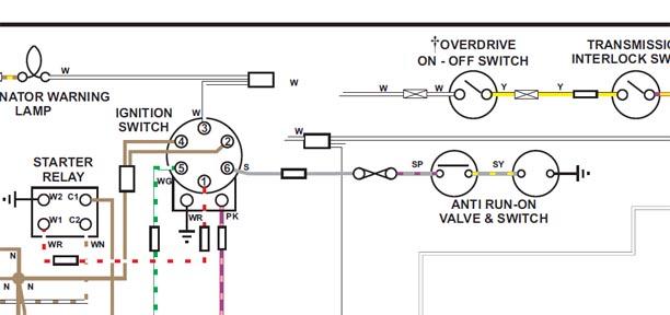
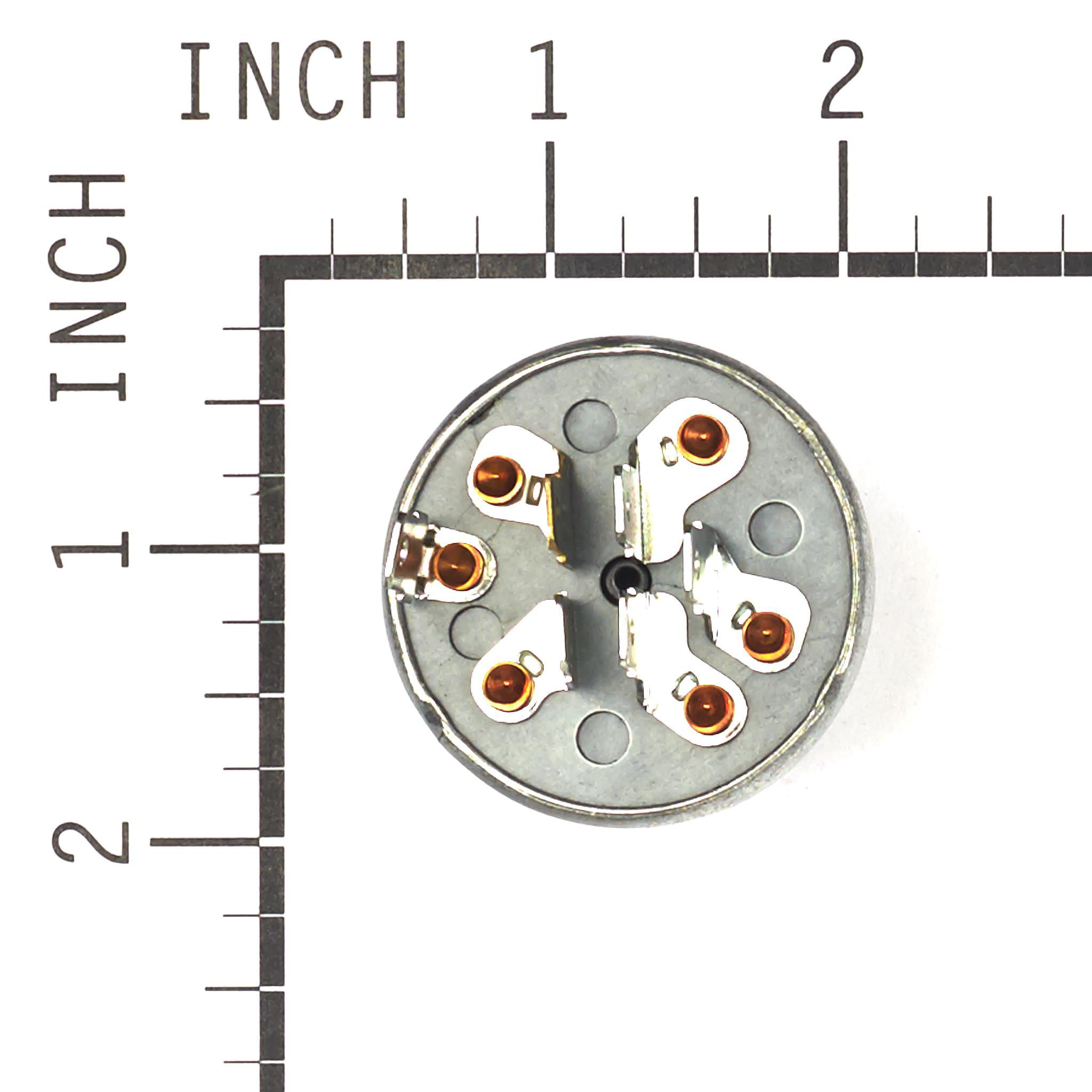
43 7 terminal ignition switch wiring diagram
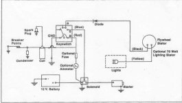
PDF T-3986 GS EE 98 Adde | WIRING DIAGRAMS The wiring diagrams are grouped into individual sections. Warning: be sure that the ignition switch always is in the off position, unless the procedure • Connectors are fully seated • Spread terminals, or terminal push out • Terminals in the wiring assembly are fully... Wiring diagrams to help you understand how it is done. Jun 12, 2018 — wiring diagrams for S/G battery ignition systems with a four terminal ... I used the 3 terminal ignition switch diagram, for the 867.25 posts · I have a few basic electrical system diagrams that are helpful in understanding how the ...
PDF DI.fm | Wiring Diagrams and Trouble Diagnosis 102 Wiring Diagram — COMM — . 103 Terminals and Reference Value for AV Control Uni.t 107 Terminals and Reference Value for Display With the ignition switch in the ACC or ON position, power is supplied q through 10A fuse [No. 21, located in the fuse block (J/B) No. 1] q to...
7 terminal ignition switch wiring diagram
Fuse Box Diagram Mercedes-Benz E-Class (W211; 2003-2009) Fuse box diagram (location and assignment of electrical fuses and relays) for Mercedes-Benz E-Class (E200, E220, E230 In this article, we consider the third-generation Mercedes-Benz E-Class (W211), produced from 2003 to 2009. Here you will find fuse box diagrams of Mercedes-Benz E200, E220... PDF Electrical wiring diagram Overall M electrical. Wiring diagram. Provides circuit diagrams showing the circuit When the ignition SW is turned on, current flows from the GAUGE fuse to TERMINAL 8 of the light failure SWITCH, IGNITION A key operated switch with several positions which allows various circuits... PDF Foreword | how to read wiring diagrams ABBREVIATIONS. WIRING DIAGRAM Symbols used in WIRING DIAGRAM are shown below: CONNECTOR This shows that these connectors white 6 terminal Ignition switch "OFF". • Doors, hood and trunk lid/back door closed. • Pedals are not depressed and parking brake is released.
7 terminal ignition switch wiring diagram. Interfacing Seven Segment Display on TinkerCad... - Instructables Each one of the seven LEDs in the display is given a positional segment with one of its connection pins being brought straight out of the rectangular plastic package. These individually LED pins are labelled from a through to g representing each individual LED. PDF EMR3 System description | Circuit diagrams The power supply (ignition, terminal 15) must be switched off before all work on the electrical system. Sensors and actuators must not be connected to external voltage sources for test purposes. Circuit diagram. The marking of the relay-pins is not compatible to the DEUTZ wiring diagrams. 5 Terminal Ignition Switch Wiring Diagram | autocardesign Sep 20, 2020 · 5 Terminal Ignition Switch Wiring Diagram- wiring diagram is a simplified within acceptable limits pictorial representation of an electrical circuit.It shows the components of the circuit as simplified shapes, and the power and signal connections together with the devices. Volvo Truck Workshop Manual free download... | Truckmanualshub.com Volvo truck electrical schematics; Volvo truck wiring diagrams PDF; Volvo truck fault codes PDF; DTCs; Volvo Truck Workshop Manual free download PDF. Download. Volvo Truck Wiring Diagrams PDF.
Ignition Switch Connector | O'Reilly Auto Parts | Number Of Terminals Order Ignition Switch Connector for your vehicle and pick it up in store—make your purchase, find a store near you, and get directions. Your order may be eligible for Ship to Home, and shipping is free on all online orders of $35.00+. Check here for special coupons and promotions. How to Replace an Ignition Switch: 15 Steps (with Pictures) A faulty ignition switch in your vehicle can cause several problems ranging from your car stalling and all lights going dark to the 2 Removing the Ignition Switch. 3 Installing a Replacement. Disconnect the negative terminal on the battery. Locate the battery in the engine bay or trunk of your vehicle. 1 Gang & 2 Gang, 1 Way Switch Connection / How to Wire One Gang... In this video, I have explained, how to wire 1-gang 1-way switch and 2-gang 1-way switch. This is very important for house wiring. A 1 gang switch can... How to Set up Seven Segment Displays on the Arduino - Circuit Basics Seven segment displays are used in common household appliances like microwave ovens, washing machines, and air conditioners. Seven segment displays come in a wide variety of sizes and colors. Red, blue, and green are the easiest colors to find.
Ignition Switch Wiring Diagram and Connection for Pins - ETechnoG An Ignition Switch was also known as a starter switch or start switch is a key-operated switch that is used As it controls the electrical system of the car so wiring of the ignition switch and its terminal connection is very important. Here, you can see the wiring diagram of ignition switch for 4 poles. RENAULT LAGUNA WIRING DIAGRAMS Pdf Download | ManualsLib Diagram 1 Information for wiring diagrams. Diagram 2 Starting, charging, Diesel fuel shut-off, engine cooling fan. Diagram 3 Diesel fuel heater, pre and post Page 6 Wire colours Key to items Diagram 5 BA White JA Yellow Battery 48 Line pressure sensor 56 Driver's airbag/cruise control switch Ignition... Nissan Pathfinder. Manual - part 250 INFOID:0000000009729237. Regarding Wiring Diagram information, refer to. Check wiring harness for short to ground. 1. Turn ignition switch OFF. 2. Check continuity between wheel sensor harness connector terminals of suspect wheel and ground. Chevrolet Corvette 1992 - G TESTS W CODES 5 7L PFI 1992... Car Wiring Diagrams. Turn ignition switch to ON position, and ground diagnostic test terminal "B" at ALDL connector. Chevrolet Corvette 1992 - Diagnostic Aids. With ignition switch in ON position and engine stopped, manifold pressure is equal to atmospheric pressure and signal voltage will be high.
Ignition Switch Terminal Diagram - Free Catalogs A to Z 7 Terminal Ignition Switch Wiring Diagram - Collection. 7 hours ago Ignition switch brass terminals on switch wiring diagram for 4 position universal ignition. It shows the components of the circuit as simplified shapes and the power and signal connections between the devices.
Nissan Frontier 2002 Wiring Diagram | PDF | Airbag | Seat Belt 1 L/OR Ignition switch start signal Ignition switch in START position 12. All other conditions 0. 2 Y/G Power source for head Terminal Wire Voltage. Item Condition No. color (Approx.) GI 12 G/W Ignition switch on signal Ignition switch OFF, ACC positions 0.
Caterpillar Shematics Electrical Wiring Diagram - Truck manual... Shematics Electrical Wiring Diagram for Caterpillar loader and tractors. Workshop, repair and service manuals, wiring diagrams, fault codes PDF - more than 1000+ truck manuals are available for free download!
How To 4 Terminal Ignition Switch Wiring IGNITION SWITCH Brass terminals on switch Wiring Diagram For 4 Position Universal Ignition Switch Product Code P00940. Title: Microsoft Word - Ignition switch wiring diagram Author: how to wire ignition switch. › Verified 7 days ago.
Untitled | Manualzz | Wiring diagrams In wiring diagrams, the single circuit diagrams cover each sensor and subset of the electrical system of the engine. Wire harnesses should be replaced with the appropriate replacement part. For the correct harness, refer to the specified part numbers.
PDF Chapter 1 | +12v when ignition is ON Ignition switch. Item 6 on wiring diagram. Yellow wire (terminal 6) is from the LED on the instrument panel. If the system is programmed and working correctly the LED should be flashing steadily with the ignition turned off to confirm that the immobiliser system is functioning.
PDF Wiring Diagrams VW Golf 7 - Repair Manual Golf. Current Flow Diagram. J519. Ignition/starter switch Intermittent wiper switch Multifunction display call-up button Selector lever Onboard supply control unit Steering column electronics control unit Ignition key withdrawal lock solenoid Fuse 41 on fuse holder C 2-pin connector 6-pin connector 6-pin...
How do I test the 7 prong ignition switch, 1 day, yes, no Sept 19, 2017 — With a wiring diagram I can help you test your ignition switch. ... between these two terminals only when your switch is in start position.1 answer · Top answer: In run position there should continuity between (L) and (A2).
PDF GM/opel wiring | ecu acdelco E67 diagram Ecu acdelco E98 bootpin recovery diagram. Ecu delphi DCM3.7AP diagram. Ecu acdelco E92 wiring diagram.
7 Terminal Ignition Switch Wiring Diagram - Wirings Diagram Volvo 740 1989 - Wiring Diagrams - 7 Terminal Ignition Switch Wiring Diagram. The diagram provides visual representation of a electrical structure. There are just two things which are going to be found in almost any 7 Terminal Ignition Switch Wiring Diagram.
Jeep Cherokee :: Online Manual Jeep Ignition switch & lock cylinder. Ignition system - 2.5L w/renix electronic ignition. Symptom check list. System wiring diagrams. Tire/wheel certification label incorrectly printed.
PDF At Section 83 TCM Terminals and Reference Value . 106 trouble diagnosis for power supply ... 110 Wiring Diagram — AT 1. If the ignition switch stays "ON" after repair work, be sure to turn ignition switch "OFF" once. Wait at least 5 seconds and then turn it "ON" (engine stopped)...
Part 1 -How to Test the GM Ignition Control Module (1995-2005) Switching Signal Circuit. This wire (circuit) comes from the ignition module. The following ignition system circuit diagram may be of help: Ignition If you'd like to have access to a wiring diagram, ignition component connector pin-outs, and the entire testing procedure in one place, then take a...
PDF Foreword | how to read wiring diagrams ABBREVIATIONS. WIRING DIAGRAM Symbols used in WIRING DIAGRAM are shown below: CONNECTOR This shows that these connectors white 6 terminal Ignition switch "OFF". • Doors, hood and trunk lid/back door closed. • Pedals are not depressed and parking brake is released.
PDF Electrical wiring diagram Overall M electrical. Wiring diagram. Provides circuit diagrams showing the circuit When the ignition SW is turned on, current flows from the GAUGE fuse to TERMINAL 8 of the light failure SWITCH, IGNITION A key operated switch with several positions which allows various circuits...
Fuse Box Diagram Mercedes-Benz E-Class (W211; 2003-2009) Fuse box diagram (location and assignment of electrical fuses and relays) for Mercedes-Benz E-Class (E200, E220, E230 In this article, we consider the third-generation Mercedes-Benz E-Class (W211), produced from 2003 to 2009. Here you will find fuse box diagrams of Mercedes-Benz E200, E220...











0 Response to "43 7 terminal ignition switch wiring diagram"
Post a Comment