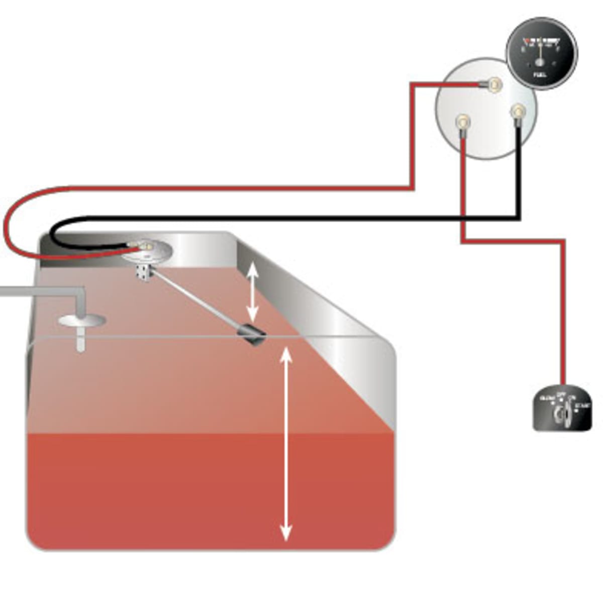
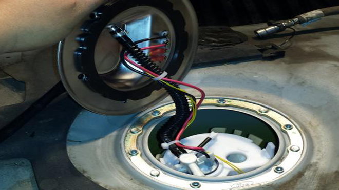
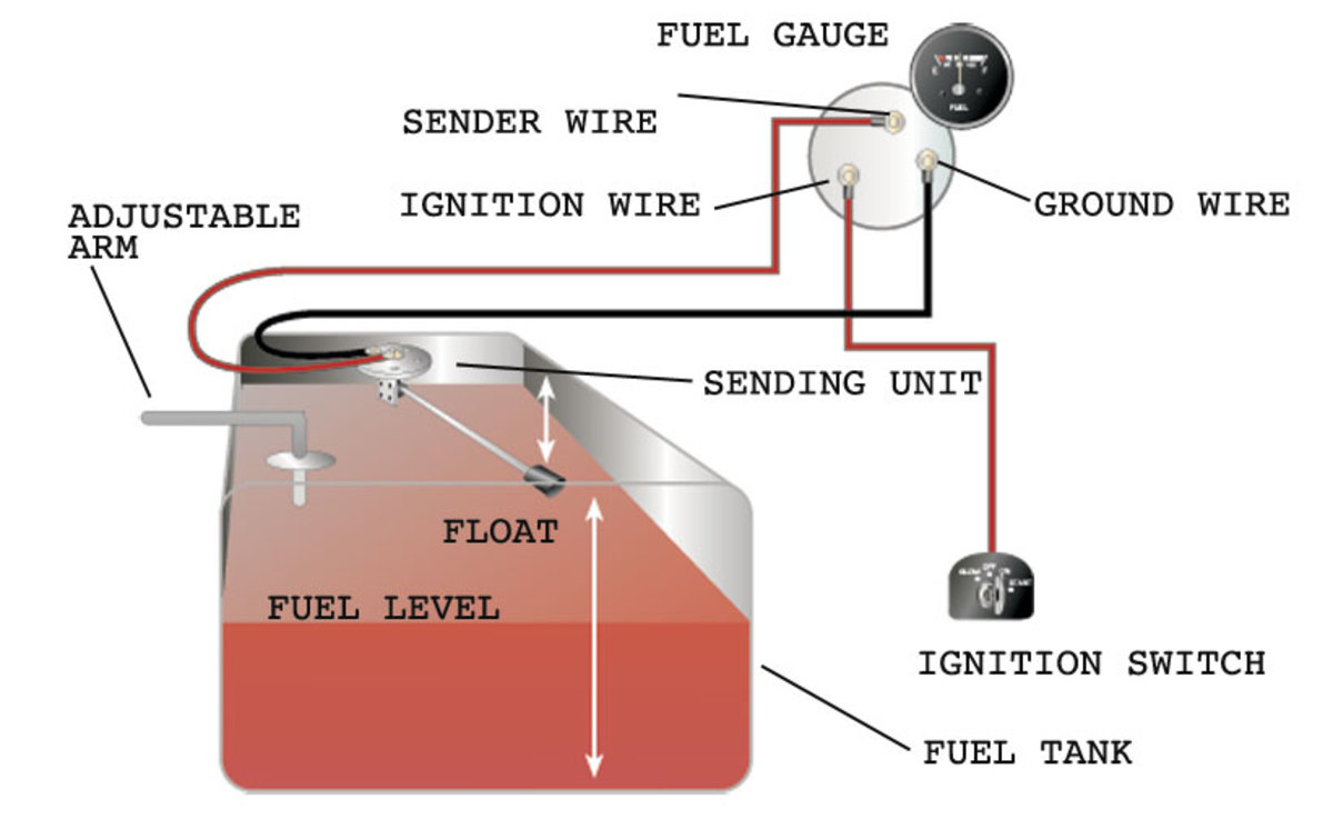
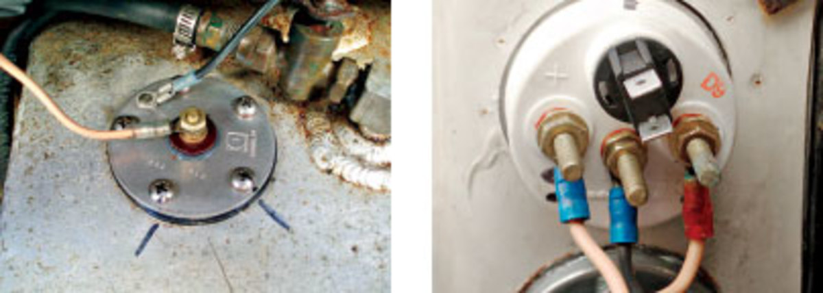
44 fuel cell sending unit wiring diagram
› instruction › fuel-cellsFuel Cells - speedmaster79.com Prior to use, flush your fuel cell with the fuel you will be using. If your fuel cell came with a sending unit installed, connect the terminals. The signal wire from the fuel gauge connects to the S terminal; the ground wire connects to the G terminal. Routinely check the fittings & cap ring for leaks and tighten as needed. How to calibrate Sending Units - HARMON RACING CELLS There are two types of sending units we offer, 2-wire (2-terminal) and 3-wire (3-terminal). Although they both measure fuel level the same way, they differ in how the unit is powered (and hence, the number of terminals on the unit). With 2-wire senders the Send terminal both powers the unit and transmits the signal to the display.
2001 Bayliner - Fuel Sender Green/Yellow wire?-gctid823808 ... A green wire will be a bonding wire. It'll usually be connected to the metal fuel tank via a tab welded to the tank near the fuel sending unit, the tab has a screw that secures the green wire to it. As Fritz said the green wire will be connected into the negative side of the 12 volt system somewhere in the engines wire harness or engine block.
Fuel cell sending unit wiring diagram
› documentFuel Safe Fuel Level Sending Unit Set-Up | Pegasus Auto ... Mar 26, 2015 · Disconnect the battery and connect the sending unit as shown in the wiring diagram, but do not install it in the fuel cell. Turn on the ignition and wait five minutes for the meter to warm up. Turn both the “Full” and “Empty” screws to the full CW (clockwise) direction. Faria Fuel Gauge Wiring Diagram IS, A, FB-Sentry - WD - Wiring Diagram, Wiring Diagram IS, B, Multifunction Gauge - 5 inch - Tachometer, Voltmeter, Fuel Level, Owner's Manual. How to Install a Moeller Fuel Gauge. Electric Sending Unit to Fuel Gauge Wiring Diagram and Industry Recommendations. Fuel Gauge wiring diagram. Page of links to the technical section for Faria gauges. How to Test and Replace your Fuel Gauge and Sending Unit ... Check the wiring diagram that comes with the kit and mark the back of the new fuel gauge with symbols for each post: "S" for the sender, "G" or "—" for the ground, and "I" for the ignition. Install the new gauge, reconnect the wiring and turn on the power. The fuel gauge should now show the correct fuel level in the tank.
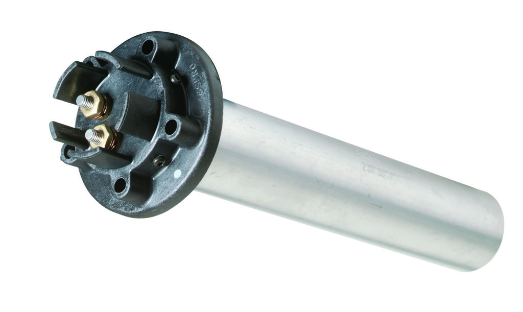
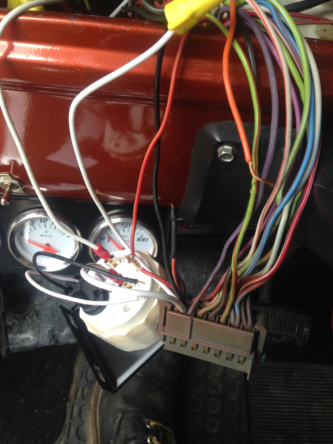
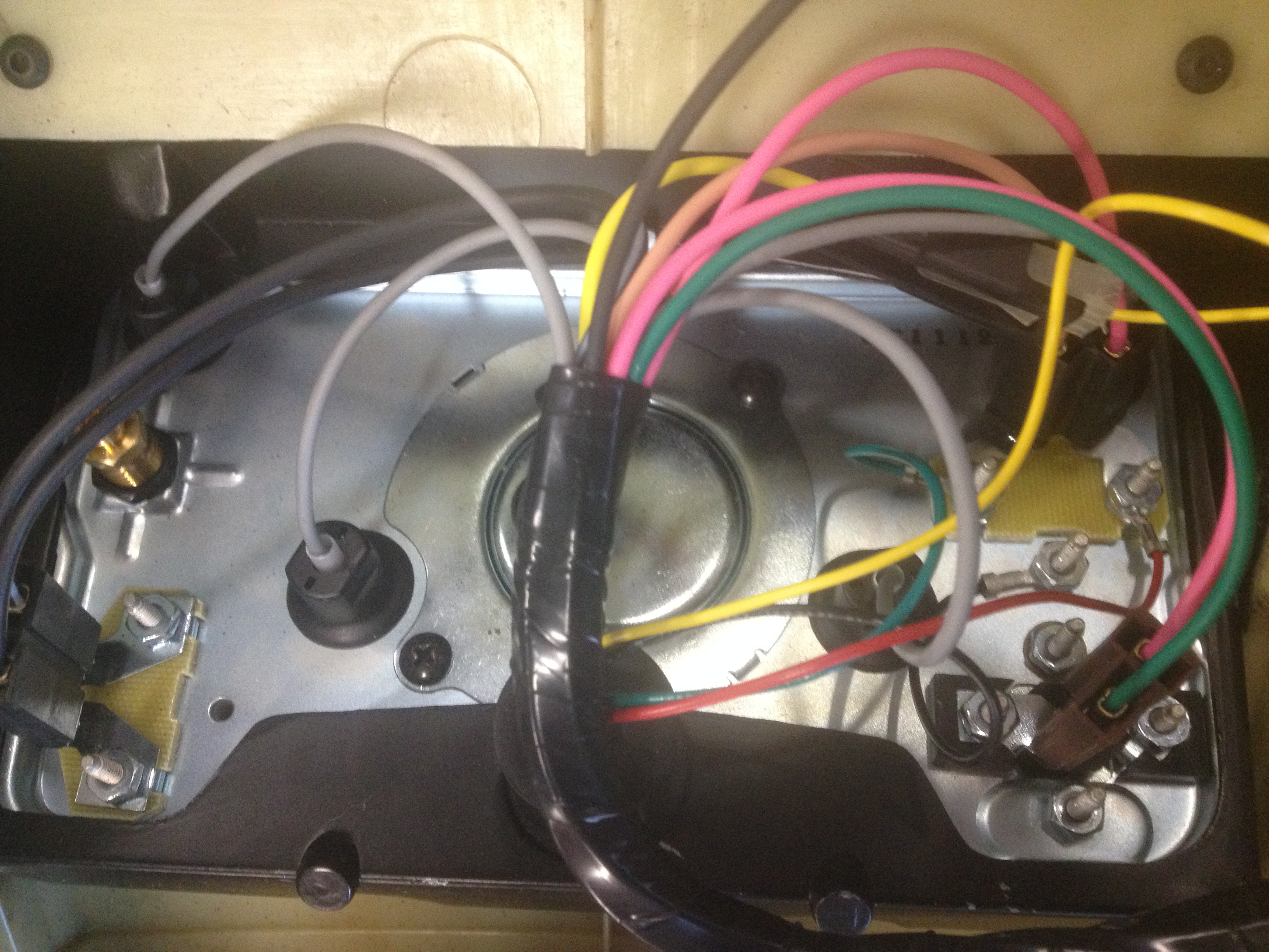
Fuel cell sending unit wiring diagram. Ultimate fuel system guide for 73-87 C10 & K10 Squarebody ... Fuel Sending Unit(s) - Select which side the fuel filler door is located Spectra Premium FG05M and FG05N sending units - HERE Conversion fittings to attach PTFE AN fuel lines to the sending unit(s) 1 of each needed per sending unit. 5/16 Hardline tube to AN6 Adapter fitting - HERE. 3/8 Hardline tube to AN6 Adapter fitting - HERE. Fuel Pump(s) How To Test a Fuel Sending Unit & Gauge | Old School Way An old-school approach to quickly diagnose your fuel sending unit and the gauge. Most times, the wiring is bad. Use this video as a reference.Heres a link to... Fuel Sending Unit Wiring Diagram - Cadician's Blog Fuel Tank Schematic Diagram | Wiring Library - Fuel Sending Unit Wiring Diagram Wiring Diagram comes with several easy to stick to Wiring Diagram Guidelines. It really is meant to assist all the average person in creating a correct method. These instructions will likely be easy to grasp and apply. 0-90 Ohms Fuel Gauge - Fuel Cell Sending Unit - Fuel Sender Buy Today! | 0-90 Ohms Fuel Gauge - Fuel Cell Sending Unit - Fuel Sender. COVID-19 UPDATE - Fuel Safe Systems remains open, taking orders, manufacturing, and shipping product. Cart . Log In . Fuel Safe Systems Online Store. Search: Search. 800-433-6524 Free Shipping on Online Orders Over $250 Motorsports. Fuel Cells. Universal. Pro Cell® ...
schematron.org › equus-fuel-gauge-wiring-diagramEquus Fuel Gauge Wiring Diagram - schematron.org Description: Gm Fuel Gauge Schematic Fuel Gauge Troubleshooting Wiring Diagrams with Equus Fuel Gauge Wiring Diagram, image size X px, and to view image details please click the image. Here is a picture gallery about equus fuel gauge wiring diagram complete with the description of the image, please find the image you need. › media › manualINSTALLATION INSTRUCTIONS SHORT SWEEP ELECTRIC FUEL LEVEL ... Wiring: Sending Unit Wiring: Gauge Mounting: Gauge to Sender Compatibility: Looking at the rear of the gauge, you will have 3 terminals labeled S, I, & GND. You may use 18g or 20g stranded wire for all fuel level gauge wiring. S = This connects to the sending unit in the fuel tank. **(See Sending Unit Wiring Section) I = Supply 12v, key on ... PDF Fuel Level Sender - 3 Terminal Water Level Sender - 3 ... 3) SEND and NEG wires reversed on Sending Unit. 4) Meter not grounded properly. 5) SEND wire is touching NEG terminal or wiring 6) Center rod on fuel units touching the outside tube. 7) Unit not calibrated. Water tank only: End of tube not sealed properly. WATER TANK SENDERS 1. The water tank units are not interchangeable with the fuel units. 2. › static › filesFuel Levels Ender Instructions - JAZ Products (approximately 2") from hardware, sides of fuel cell and mount strap recesses. Drill 1-1/2' hole through cell with hole saw. Insert sending unit through 1-1/2' hole and use as template for drilling the 5 mounting holes. Use the 7/32' drill bit to drill the mounting holes. Remove sending unit and clean inside cell thoroughly. (CELL MUST BE FREE ...
Kus Fuel Gauge Wiring Diagram - schematron.org This KUS fuel & liquid sender is designed to work with gauges using the on the same resistance - use your gauges wiring diagram to correctly install the wires.The fuel tank should be grounded and the sender wire pink should be connected to the sender terminal on the sending unit this is the correct wiring. Gas tank sending unit wiring diagram help | Boating Forum ... 441. Jun 10, 2009. #5. Re: Gas tank sending unit wiring diagram help. 1. with key on, bridge or connect center wire on tank (usually pink) to the tank ground wire. If the tank has a spade connector, make sure its clean and tight. a. if Gage pegs to full, problem is in the sender in the tank (most likely) b. if gage does not move, ground the ... PDF Installation Instructions for 153xx Fuel Cells, Fuel Cell ... ALL FUEL CELLS MUST BE VENTED PROPERLY. If your cell has a Sending Unit, it is for a 0-90 OHM gauge 0 ohms = EMPTY 90 ohms = FULL Sending units work with most GM factory gauges with 0-90 OHMS. The center post wires directly to the gauge and you must ground the sending unit from one of the outside bolts of the sending unit to your frame ... Moeller Fuel Gauge Wiring Diagram The fuel tank should be grounded and the sender wire pink should be connected to the sender terminal on the sending unit this is the correct wiring. The sending unit will ground through the mount screws. The fuel gauge reads the resistance to ground check the wires on the back of the gauge pink to S terminal and black to G terminal.
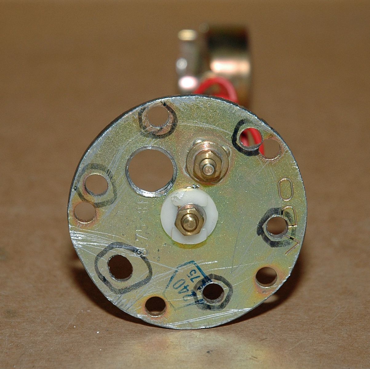
Installing A Fuel Gauge and Sender | Hotrod Hotline I had to use the sending unit supplied with my VDO fuel gauge because it registers empty at 10 ohms and full at 180 ohms, the same as new VDO gauge senders. The standard aftermarket senders now measure the fuel capacity at 33 ohms empty and 240 ohms at full. Bolt pattern was rotated slightly to match the six-hole pattern on my stock '32 tank.
fuel cell sending unit wiring | Chevy Nova Forum 7,014 Posts. #4 · Dec 14, 2015. The sender must be matched to the gauge and with an unknown sender you need to remove it from the fuel cell and do some tests with an ohmmeter. We could assume all day what might be in there but you might as well do it right. Once that is known are you wanting to run the original gauge up front ?.
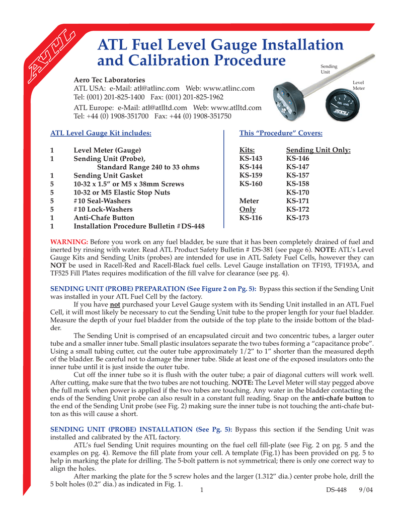
PDF ATL Fuel Level Sender Probes - Rage Motorsport 1. With the probe out of the Fuel Cell, wire up the Fuel Level Sender Probe to the ATL Dashboard, or Data Logger, as per the wiring diagram (Page 4). Connect the calibration wire (white) to ground, or onto the shaft of the Sensor Probe, and then power up the Sender with a 12V supply.
Rci Fuel Cell Sending Unit Wiring Diagram - Wiring Diagram Rci Racing 2161a Aluminum Street Fuel Cells Summit. Sdmaster 1 130 013 Aluminum Fuel Cell 20 Gallon. Gen Ii Stealth Fuel Tank 82 92 Camaro Aeromotive Inc. Gauge and sending unit wiring diagram fuel to cell rci equus rewiring external pump an atl level sender probes racing 7060b 340 stealth 6 gallon educate me on how a cells at summit bracket ...
› threads › fuel-sending-unit-wiring-diagramFuel sending unit wiring diagram - Toyota Tacoma Forum May 16, 2007 · Enola, I cant seem to find any wiring diagrams for the sending unit / gas gauge for my 00 Tacoma. I need to know the wiring so i can wire up my fuel cell. Thanks, Dave
Fuel Gauge Sending Unit Wiring Diagram - autocardesign Fuel Gauge Sending Unit Wiring Diagram - wiring diagram is a simplified customary pictorial representation of an electrical circuit. It shows the components of the circuit as simplified shapes, and the skill and signal connections amid the devices. A wiring diagram usually gives opinion not quite the relative outlook and arrangement of ...
Fuel Sending Unit Wiring For Fuel Cells - Hot Rod Forum 2,354 Posts. #3 · Dec 29, 2003. Awesum is correct. The gauge and sending units must be compatible. Also, you did not mention what material your fuel cell wil be constructed from. Any thing other than steel will require grounding of the sending unit. Most fuel cells come without sending units so if you do not have one with your old gauge, then ...
2020cadillac.com › tag › fuel-gauge-sending-unit-wiring-diagramFuel Gauge Sending Unit Wiring Diagram - Cadician's Blog Dec 23, 2020 · fuel gauge sending unit wiring diagram – You’ll need an extensive, skilled, and easy to comprehend Wiring Diagram. With this sort of an illustrative guide, you are going to be able to troubleshoot, prevent, and complete your tasks without difficulty.
How to Wire a Fuel Sending Unit - It Still Runs Step 4. Run the wire from the post labeled "ignition" on the sender to the ignition switch. There should be a post labeled "sndr" on the switch. Solder the end of the wire to this post using silver core solder, and insulate the connection using spray-on insulation once the solder cools. Run the other wire from the sending unit to the nearest ...
Fuel Cell Sending Unit Wiring Diagram Database Fuel Cell Sending Unit Wiring Diagram. To properly read a electrical wiring diagram, one offers to learn how the particular components within the system operate. For example , when a module is powered up and it also sends out a signal of half the voltage in addition to the technician will not know this, he'd think he offers a problem, as he ...
PDF Fuel Level Sender Installation Instructions VI. Refer to Diagram E. If no holes exist in the fuel tank and you have the optional mounting kit (226-551) cut a 2.332" (59mm) hole in the top of the tank. Diagram E 1. Pick up fuel sender and slide the rubber gasket up to the bottom of the fuel sender flange. Next, slide the second flange over fuel sender to bottom of rubber
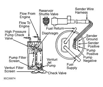
Troubleshooting And Replacing Your Ford Fuel Gauge Here is a picture of a sending unit on a 1988 Bronco II wiring diagram: How It works: ... Ground the sending unit wiring to a good chassis ground (instead of the sending unit housing) and watch the gauge. ... The same goes for after market sending units that you might get with a fuel cell. Check your instructions or call manufacturer for ...
How to Test and Replace your Fuel Gauge and Sending Unit ... Check the wiring diagram that comes with the kit and mark the back of the new fuel gauge with symbols for each post: "S" for the sender, "G" or "—" for the ground, and "I" for the ignition. Install the new gauge, reconnect the wiring and turn on the power. The fuel gauge should now show the correct fuel level in the tank.
Faria Fuel Gauge Wiring Diagram IS, A, FB-Sentry - WD - Wiring Diagram, Wiring Diagram IS, B, Multifunction Gauge - 5 inch - Tachometer, Voltmeter, Fuel Level, Owner's Manual. How to Install a Moeller Fuel Gauge. Electric Sending Unit to Fuel Gauge Wiring Diagram and Industry Recommendations. Fuel Gauge wiring diagram. Page of links to the technical section for Faria gauges.
› documentFuel Safe Fuel Level Sending Unit Set-Up | Pegasus Auto ... Mar 26, 2015 · Disconnect the battery and connect the sending unit as shown in the wiring diagram, but do not install it in the fuel cell. Turn on the ignition and wait five minutes for the meter to warm up. Turn both the “Full” and “Empty” screws to the full CW (clockwise) direction.











0 Response to "44 fuel cell sending unit wiring diagram"
Post a Comment