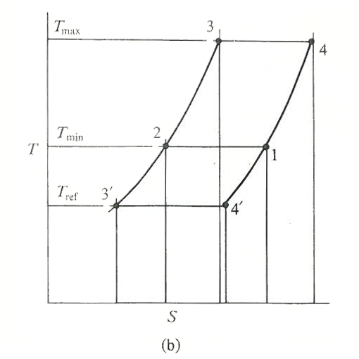
45 stirling cycle ts diagram
Thermodynamic Stirling Cycle and Stirling Engine - Part 1 ... Processes of Ideal Stirling Cycle. The ideal Stirling cycle comprises of two isothermal processes and two constant volume processes. The rejection of heat and absorption of heat takes place at constant temperature. Here are various processes of the Stirling cycle; these have been described with the piston-cylinder diagram and P-V diagram. Stirling cycle PV and TS diagram and efficiency - YouTube Stirling cycle PV and TS diagram and efficiency | Stirling cycle efficiency derivation - YouTube.
PDF Are P-V and T-S Diagrams Meaningful for Regenerative ... difficulty will be ignored here for P-V and T-S diagrams, and we will keep the sharp corners. As an example, consider the ideal single-stage regenerative cycle shown in Fig. 3. This cycle has two isothermal steps, compression and expansion, and two isochoric steps, flow through the recuperator. This is the idealized Stirling cycle.
Stirling cycle ts diagram
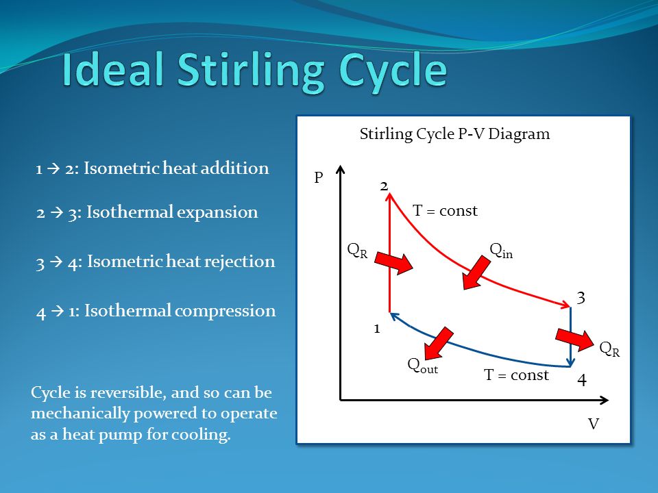
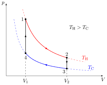
Stirling cycle | Efficiency, P-V & T-S Diagrams | Heat ... Below are P-V and T-S Diagrams of the Stirling Cycle. Stirling Cycle is comprised of four processes Process 1-2 It is isothermal heat addition process. Volume of the system increases due to isothermal heat addition. A little drop in pressure also happens in this process. Process 2-3 It is isochoric heat removal process. Stirling Cycle: Efficiency with P-v and T-s Diagram Stirling cycle was devised by Stirling, which consists of two isothermal processes and two constant volume processes. The last two processes are performed with the help of a refrigerator to make this cycle reversible. The p-v and t-s diagrams of this cycle are shown in the figure. Let us now consider the four stages of the Stirling cycle. P-V and T-S diagrams of the Ideal Stirling Cycle ... Download scientific diagram | P-V and T-S diagrams of the Ideal Stirling Cycle from publication: Improving Power Density of Free-Piston Stirling Engines | Analyses and experiments demonstrate the ...
Stirling cycle ts diagram. Ericsson Cycle Pv and Ts Diagram - Understanding Business ... First we will see here the PV and TS diagram for Ericsson cycle, we will understand here the various processes involved and finally we will determine the thermal efficiency of the Ericsson cycle. As we can see here from PV and TS diagram, there will be two reversible isothermal processes and two reversible constant pressure processes. Stirling International - Stirling Cycle Stirling Cycle. Fig.1: the Stirling cycle; (a) P-V and T-S diagrams; (b) piston arrangement at the terminal points of the cycle; (c) time-displacement diagram. Fig. 2 (a): Stirling and Carnot P-V cycle. Fig. 2 (b): Stirling and Carnot T-S cycle. The Stirling cycle is similar, in some respects, to the Carnot cycle, as illustrated in fig.1. 斯特林循环pv和ts图-机械工程概念和原理 - 新利是什么平台,新利18平台下载 首先,我们将看到这里的PV和TS图的斯特林循环,我们将了解这里涉及的各种过程,最后我们将确定斯特林循环的热效率。. 从这里的PV和TS图可以看出,会有两个可逆等温过程和两个可逆等容过程。. 过程中,1 - 2:从状态1到状态2的等温膨胀。. 热能将从外部来源添加到这里。. 在这个过程中,体积会增加,但压力会减少。. ΔU = 0, 问1-2= W1-2= RT1日志(V2/ V1). 过程中,2 - 3:恒容 ... A Simple Approach to Heat Engine Efficiency - NASA/ADS Temperature-entropy (TS) diagrams are introduced as a way to simplify the calculation of efficiency for reversible heat engines. The equation for the efficiency of the Stirling cycle is derived from its TS diagram. The conflict over the efficiency of the Stirling cycle is thereby resolved; the standard Stirling cycle does not have an efficiency equal to the Carnot cycle efficiency.
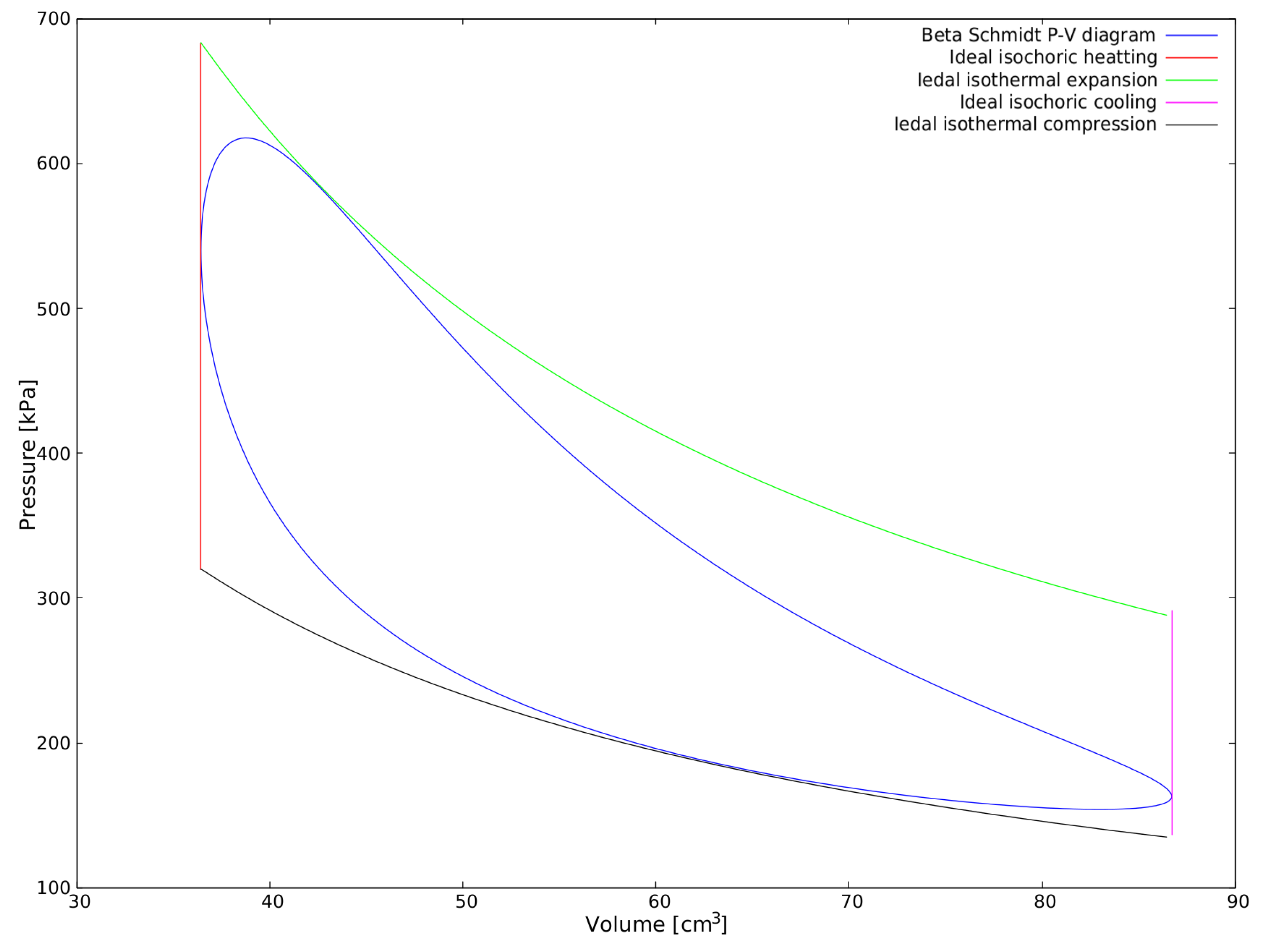
Diesel Cycle: Definition, Process, PV and TS Diagram ... So This is how diesel cycle process takes place. Diesel Cycle PV and TS Diagram: Now we will study PV and TS Diagram: Process 1-2: Reversible Adiabatic Compression Process; Process 2-3: Constant Pressure Heat addition; Process 3-4: Reversible Adiabatic Expansion Process; Process 4-1: Constant volume Heat rejection Brayton Cycle - Definition, Meaning, Efficiency, Ts, Pv ... Brayton cycle actual diagrams equations Ts Pv formula . The Brayton cycles are mainly used in jet planes, usefulness of this Cycle is tremendous due to the fact it is the backbone in driving even helicopters, and submarines. History of Brayton Cycle. PV and Ts diagram of Stirling engine cycle. | Download ... PV and Ts diagram of Stirling engine cycle. Source publication Theoretical and experimental investigation of Alfa type bio mass Stirling engine with effect of regenerator effectiveness, heat ... Atkinson Cycle, Ericsson Cycle And Stirling Cycle Stirling Cycle The Stirling cycle consists of two isothermal and two isochoric processes. The p-V and T-s diagrams of Stirling cycle has been given below: 24. Stirling Cycle The processes occurring in a Stirling Cycle is given below: a) Process 1-2: The volume of gas increases at a constant temperature.
PDF Stirling Cycle - Simon Fraser University Fig. 3-2: T-s and P-v diagrams for Stirling cycle. 1-2 isothermal expansion heat addition from external source 2-3 const. vol. heat transfer internal heat transfer from the gas to the regenerator Stirling cycle - Wikipedia The idealized Stirling cycle consists of four thermodynamic processes acting on the working fluid (See diagram to right): 1→2 Isothermal heat addition (expansion). 2→3 Isochoric heat removal (constant volume). 3→4 Isothermal heat removal (compression). 4→1 Isochoric heat addition (constant volume). Piston motion variations Temperature - Entropy Diagram for Stirling Cycle - File ... This Stirling cycle is classified by 4 idealized thermodynamic processes. First the gas undergoes isothermal compression, and then is heated at a constant volume. Next, the gas is allowed to expand at a constant temperature, and is then cooled at a constant volume. This cycle repeats and work is continually extracted from the expansion of the gas. What is Carnot Cycle - pV, Ts diagram - Definition The temperature-entropy diagram (Ts diagram) in which the thermodynamic state is specified by a point on a graph with specific entropy (s) as the horizontal axis and absolute temperature (T) as the vertical axis, is the best diagram to describe behaviour of a Carnot cycle.
What is the T-s diagram for the Carnot refrigeration cycle ...
Otto Cycle - pV, Ts Diagram | Application | nuclear-power.com pV diagram of Otto Cycle. The area bounded by the complete cycle path represents the total work that can be done during one cycle. The Otto cycle is often plotted on a pressure-volume diagram (pV diagram) and a temperature-entropy diagram (Ts diagram).When plotted on a pressure-volume diagram, the isochoric processes follow the isochoric lines for the gas (the vertical lines), adiabatic ...

Stirling Engine- The obscure jewel - Synergy Files
Rankine Cycle - Processes, Efficiency [P-v and T-s Diagram] A Carnot cycle, using steam as a working substance, is represented or p-v and t-s diagram as shown in the figure. Consider 1kg of water at pressure P1 and absolute temperature T1 as represented by point 1 in the figure. The cycle is completed by the following four processes.
Stirling International - Reverse cycle
Stirling Engine Diagrams - American Stirling Company Explanation of the Diagram Above. The thermodynamics of the idealized Stirling engine cycle (above) are easy to explain. The gas goes around the diagram and experiences these changes. 1.1. Isochoric heating: Isochoric heating means heating without moving the piston.

P-V diagram for Stirling cycle | Download Scientific Diagram
File:Stirling pV- und TS-Diagramm.svg - Wikimedia Commons File:Stirling pV- und TS-Diagramm.svg. Size of this PNG preview of this SVG file: 800 × 440 pixels. Other resolutions: 320 × 176 pixels | 640 × 352 pixels | 1,024 × 563 pixels | 1,280 × 704 pixels | 2,560 × 1,408 pixels | 1,000 × 550 pixels.
Solved Ideal Stirling Cycle Processes 1-2 and 3-4 are | Chegg.com
Answered: In a stirling cycle with an ideal… | bartleby Include the PV and TS Diagram. In a stirling cycle with an ideal generator the volume varies between 0.03 and 0.06 m^3 the maximum pressure is 2 atmosphere and temperature varies between 500 C to 250 C. The working fluid is air. Compute the network and the cycle thermal efficiency. Include the PV and TS Diagram.

MECHANICALFUNDA for Mechanical Engineer
Ericsson cycle | Efficiency, P-V & T-S Diagrams | Heat ... Ericsson cycle is a thermodynamic cycle upon which an Ericsson Engine works. Ericsson engine is a closed cycle regenerative heat engine. It works on either air or any other gas. Ericsson cycle is invented by John Ericsson. Below are P-V and T-S Diagrams of the Ericsson Cycle. Ericsson Cycle is comprised of four processes.
General discussion of Stirling engine
Thermodynamic Theory of the Ideal Stirling Engine The Stirling Engine as a Cycle. Heat engines are cyclic, and that's the case for the Stirling engine. In the case of a reciprocating engine, like what we've built, a process occurs between the hold section and the cold section, which repeats at a certain frequency.
side3
Stirling Heat Engine Ts Diagram - How Can I Build An ... The stirling cycle proper is an ideal thermodynamic cycle. Schematic diagram of the stirling heat engine cycle. The thermal regenerator and the original stirling engine incorporating a regenerator. While the stirling cycle can be very simply explained in its .
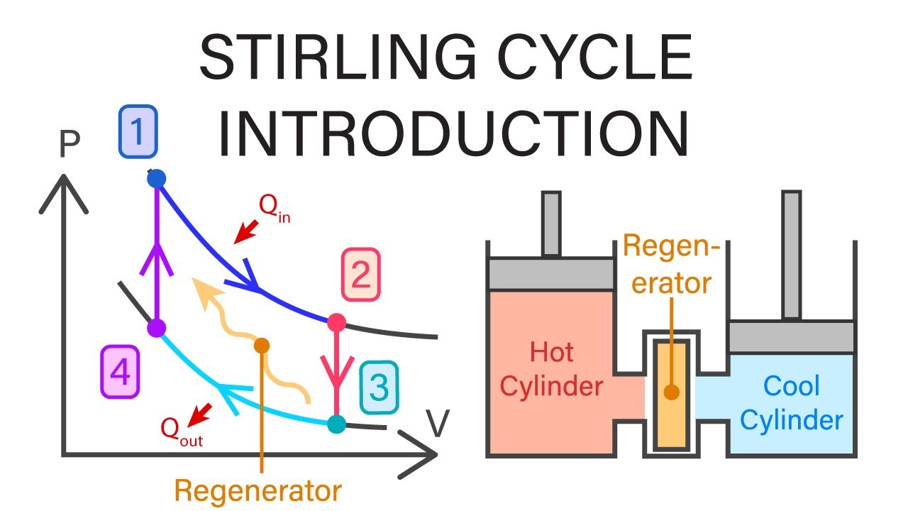
Mechanical Engineering Thermodynamics - Lec 16, pt 5 of 6: Stirling Cycle Introduction
Stirling Cycle Pv and Ts Diagram - Understanding Business ... First we will see here the PV and TS diagram for Stirling cycle, we will understand here the various processes involved and finally we will determine the thermal efficiency of the Stirling cycle. As we can see here from PV and TS diagram, there will be two reversible isothermal processes and two reversible constant volume processes.
Thermodynamic analysis and analytical simulation of the ...
Stirling cycle - zxc.wiki Stirling cycle in the pV and TS diagram Scheme of the Stirling engine comparison process The Stirling cycle consists of two isothermal changes of state and two isochoric changes of state and is usually represented with the pV and TS diagram .

Atkinson Cycle - Thermodynamics Cycle
ericsson cycle PV,TS diagram and efficiency derivation ... Please watch: "Last minute important tips for GATE 2020 exam #gate2020 #gate" --~--ericsson cycle PV , TS diagram...

Stirling Refrigeration Cycle (a) P-V diagram (b) T-S diagram ...
P-V and T-S diagrams of the Ideal Stirling Cycle ... Download scientific diagram | P-V and T-S diagrams of the Ideal Stirling Cycle from publication: Improving Power Density of Free-Piston Stirling Engines | Analyses and experiments demonstrate the ...

Solved The Stirling cycle, represented on the PV diagram ...
Stirling Cycle: Efficiency with P-v and T-s Diagram Stirling cycle was devised by Stirling, which consists of two isothermal processes and two constant volume processes. The last two processes are performed with the help of a refrigerator to make this cycle reversible. The p-v and t-s diagrams of this cycle are shown in the figure. Let us now consider the four stages of the Stirling cycle.

Stirling engine Stirling cycle Pressure volume diagram ...
Stirling cycle | Efficiency, P-V & T-S Diagrams | Heat ... Below are P-V and T-S Diagrams of the Stirling Cycle. Stirling Cycle is comprised of four processes Process 1-2 It is isothermal heat addition process. Volume of the system increases due to isothermal heat addition. A little drop in pressure also happens in this process. Process 2-3 It is isochoric heat removal process.

PV and Ts diagram of Stirling engine cycle. | Download ...

Carnot vs Stirling (9/15/2014)
About the Efficiency of the Regenerator in the Stirling Engine
Stirling International - Reverse cycle

Thermodynamic Stirling cycle: a) P-V diagram, b) T-S diagram ...

Stirling Cycle - an overview | ScienceDirect Topics

ERICSSON CYCLE PV AND TS DIAGRAM - UNDERSTANDING BUSINESS ...
Energies | Free Full-Text | Stirling Engine Configuration ...
Stirling Cycle and Engines - ppt video online download

Stirling Refrigeration Cycle (a) P-V diagram (b) T-S diagram ...

Underwater striling engine design with modified one ...

Stirling Cycle - Efficiency Explaination with P-v and T-s Diagram

What is Stirling Cycle? - ExtruDesign

File:Stirling Cycle.png - Wikimedia Commons
Stirling cycle - Wikipedia
Solved] Carnot Cycles a- Discuss the Carnot cycle in P-V and ...

How It Works; | kingorisolomon

Stirling Engine Phone Charger — eric j. gonzalez
Energies | Free Full-Text | Efficiency Reduction in Stirling ...

Numerical thermodynamic model of alpha-type Stirling engine ...

Carnot vs Stirling (9/15/2014)
Improving Free-Piston Stirling Engine Power Density

Solved The Stirling cycle, represented on the PV diagram ...
Thermodynamic Theory of the Ideal Stirling Engine

File:Stirling-cycle-efficiency-derived.svg - Wikimedia Commons

Notes on Stirling Cycle
Analysis and comparison of solar-heat driven Stirling ...

STIRLING CYCLE PV AND TS DIAGRAM - UNDERSTANDING BUSINESS ...

P-V and T-S diagrams of the Ideal Stirling Cycle | Download ...

P-V diagram of the Stirling cycle and T-s diagram (inset ...

The following statements are for Stirling engine and Carnot ...
0 Response to "45 stirling cycle ts diagram"
Post a Comment