43 in a state transition diagram, the circle to the left is the final state.
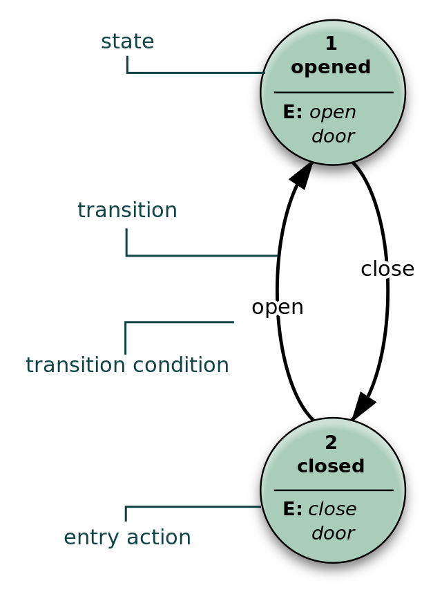
State Machine Diagram - UML 2 Tutorial | Sparx Systems The initial state is denoted by a filled black circle and may be labeled with a name. The final state is denoted by a circle with a dot inside and may also be labeled with a name. Transitions. Transitions from one state to the next are denoted by lines with arrowheads. A transition may have a trigger, a guard and an effect, as below. State Transition Diagram with example in software ... In a state transition diagram, the circle to the left is the final state. True/False Answer: False Topic Covered State Transition Diagram with example in software engineering. Prof.Fazal Rehman Shamil (Available for Professional Discussions) 1. Message on Facebook page for discussions, 2. Video lectures on Youtube 3.
sad chapter 6 Flashcards - Quizlet In a state transition diagram, the circle to the left is the final state. False A class diagram resembles a horizontal flowchart that shows the actions and events as they occur. False If ____ are similar to adjectives that describe the characteristics of an object, objects are similar to nouns. attributes A(n) ____ is a specific member of a class.

In a state transition diagram, the circle to the left is the final state.
SysML: How to Use State Diagrams to Model Systems Behavior The final state of a state machine diagram is shown as concentric circles. An open-loop state machine represents an object that may terminate before the system terminates, while a closed-loop state machine diagram does not have a final state; if it is the case, then the object lives until the entire system terminates. Example: Events alexander-goers.de › rocks-in-a-circle-meaningPage Not Found The diagram presents all the diatonic major and minor keys, in order, based on the amount of sharps or flats. of 11. My next circle was a small one under a rock overhang on a cliff near Black Earth, Wisconsin, which, from 1980-1983, I primarily used for personal The Nabta stone-circle is the only megalithic construction of its kind in all Egypt. UML State Machine Diagrams - Overview of Graphical Notation State Machine Diagrams. State machine diagram is a behavior diagram which shows discrete behavior of a part of designed system through finite state transitions. State machine diagrams can also be used to express the usage protocol of part of a system. Two kinds of state machines defined in UML 2.4 are . behavioral state machine, and; protocol state machine
In a state transition diagram, the circle to the left is the final state.. writingcenter.unc.edu › tips-and-toolsUnderstanding Assignments – The Writing Center • University ... The Writing Center Campus Box #5135 0127 SASB North 450 Ridge Road Chapel Hill, NC 27599 (919) 962-7710 writing_center@unc.edu Nondeterministic finite automaton - Wikipedia In automata theory, a finite-state machine is called a deterministic finite automaton (DFA), if . each of its transitions is uniquely determined by its source state and input symbol, and; reading an input symbol is required for each state transition. A nondeterministic finite automaton (NFA), or nondeterministic finite-state machine, does not need to obey these restrictions. › articles › s41567/021/01474-yReviving a failed network through microscopic interventions ... Jan 20, 2022 · As our final example (Fig. 6 and Supplementary Section 3.3), we consider the gut microbiome, a microbial community whose functional state has been shown to crucially impact human health 32,33. A Real-World Example of the State Transition Diagram ... This diagram demonstrates the status progression of the submitted thesis. Starting from the left, we see the first status is "Pre-Upload". This is before the thesis is uploaded by the student. The circle following that status is the "Thesis Uploaded" event. Any circles like this one that have a double border around it are known as events.
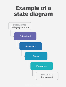
A simple guide to drawing your first state diagram (with ... 10.03.2022 · Each diagram usually begins with a dark circle that represents the initial state and ends with a bordered circle that represents the final state. Rectangles with rounded corners denote a state, and each one includes a label with the name of the state. Transitions are marked with arrows that link one state to another, showing how the states change. You’ll find a run … State Transition Diagram - an overview | ScienceDirect Topics The state transition diagram also illustrates the states and transitions of the communication protocol between the recipe phase and the equipment phase. The phase logic must adhere to the rules depicted in the state transition diagram. Only valid state transitions as depicted in Figure 8.6 may be utilized. Though the configuration of the phase logic will vary from site-to-site, the … How to Draw a State Machine Diagram in UML | Lucidchart Click on "Shapes" in the upper-left corner of your window and check "UML." The UML shape libraries will then appear on the left side of your window. Scroll down for the state diagram library and drag out a black circle to start the diagram. This circle indicates the initial state. Diagramming is quick and easy with Lucidchart. Chapter 6 - Object Modeling MULTIPLE CHOICE - Academia.edu F 21. In a state transition diagram, the states appear as rounded rectangles with the state names inside. T 22. In a state transition diagram, the circle to the left is the final state. F 23. A class diagram resembles a horizontal flowchart that shows the actions and events as they occur. F 24.
State Transition Diagram - an overview | ScienceDirect Topics The state transition diagram is abstract in that it uses states labeled {S0, S1, S2, S3} and outputs labeled {red, yellow, green}. To build a real circuit, the states and outputs must be assigned binary encodings. Ben chooses the simple encodings given in Tables 3.2 and 3.3. PDF Drawing Finite State Machines in LATEX and TikZ A Tutorial Drawing Finite State Machines in LATEX and TikZ A Tutorial Satyaki Sikdar and David Chiang ssikdar@nd.edu Version 3 January 17, 2018 1 Introduction \LATEX (pronounced lay-tek) is an open-source, multiplatform document preparation system for producing professional-looking documents....It is particularly suited to producing long, structured documents, and is 3SL Reference: SysML Modelling - State Machine Diagram The Initial Pseudo-State symbol has a single exit transition arrow. Final State: The Final State identifies the final active state, in a specific region, of a Block's state-based behaviour. The Final State's symbol name is displayed or hidden on the diagram by using the Hide name component checkbox in the Control sidebar. The Final State symbol ... Guidelines: Statechart Diagram - University of Houston ... A statechart diagram shows a state ... A final state is represented as a filled black circle surrounded by an unfilled circle. Initial and final states are really pseudostates. Neither may have the usual parts of a normal state, except for a name. A transition from an initial state to a final state may have the full complement of features ...
State transition diagram for the six states in the model ...
PDF 5 Steps to Draw a State Machine Diagram Tutorial - 5 Steps to Draw a State Machine Diagram Page 5 of 11 7. Release the mouse button. In the popup pane, select Transit -> Final State. This creates a final state. 8. Click a self-transition on the state account with funds. Move your mouse pointer over the state account with funds and click on the Resource Catalog button. 9.

Guidelines: Statechart Diagram
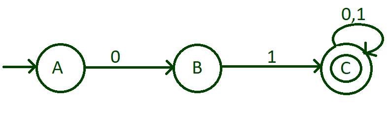
PDF Deterministic Finite Automata (DFA) Such a graph is called a state transition diagram. • One state is initial (denoted by a short incoming arrow), and several are final/accepting (denoted by a double circle). For every symbol a a emanating from every state. • • Automata are string processing devices. The arc from q 1

State Machine Diagram - UML 2 Tutorial | Sparx Systems
programming_2 - Murray State University The transition labeled else represents any symbol not explicitly referenced by another transition. The transtion labeled all makes S 3 a trap state. The state S 2 (with bold border) is the accept state. Check the final state, when you have finished scanning the string. If you are in S 2 then you accept the string as a valid integer otherwise you reject it as a non-integer string.

State Machine Diagram in UML | What is Statechart Diagram?
Predictive Parser in Compiler Design - GeeksforGeeks 18.03.2021 · Make a transition diagram(DFA/NFA) for every rule of grammar. Optimize the DFA by reducing the number of states, yielding the final transition diagram. Simulate the string on the transition diagram to parse a string. If the transition diagram reaches an accept state after the input is consumed, it is parsed. Consider the following grammar –

StateWORKS -> Publications -> Technical Notes -> What's All ...
5.1 FSM with outputs - University of Illinois Urbana-Champaign The state diagram in Fig 1 shows a FSM with input alphabet 0,1 and output alphabet p,q,r. The states are A (the starting state), B and C. To see how the FSM works let's find the output corresponding to the input string 0110101. The leftmost symbol in the string is fed in first. The FSM is initially in its starting state A and when input 0 is received, it produces output p and moves to …

State Machine Diagram - UML 2 Tutorial | Sparx Systems
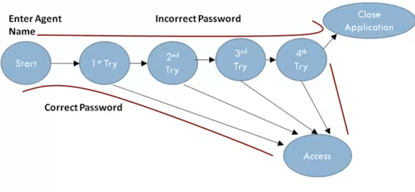
State-Transition Testing | Section I - Black Box Testing ... Information in the state-transition diagrams can easily be used to create test cases. Four different levels of coverage can be defined: Create a set of test cases such that all states are "visited" at least once under test. The set of three test cases shown below meets this requirement. Generally this is a weak level of test coverage.
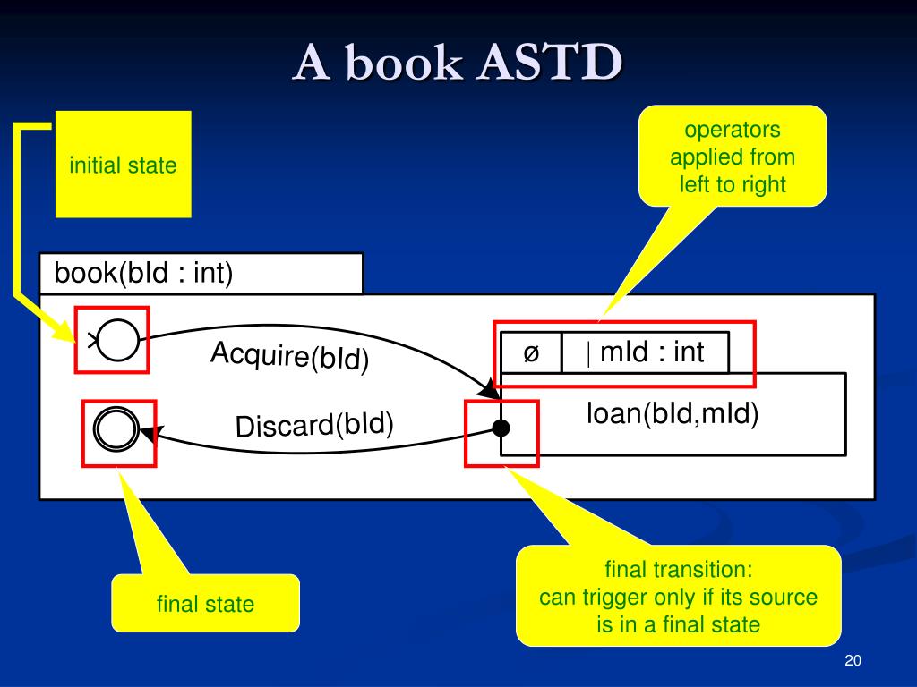
PPT - Statecharts for the many: Algebraic State Transition ...
State Machine Diagram Tutorial - Lucidchart Each state diagram typically begins with a dark circle that indicates the initial state and ends with a bordered circle that denotes the final state. However, despite having clear start and end points, state diagrams are not necessarily the best tool for capturing an overall progression of events. Rather, they illustrate specific kinds of ...
Finite State Machines | Sequential Circuits | Electronics ...
What is State Machine Diagram? The final state of a state machine diagram is shown as concentric circles. An open loop state machine represents an object that may terminate before the system terminates, while a closed loop state machine diagram does not have a final state; if it is the case, then the object lives until the entire system terminates. Example: Events

State transition diagram: Si denotes the state of the robot ...
In a state transition diagram the states appear as rounded ... In a state transition diagram the states appear as In a state transition diagram, the states appear as rounded rectangles with the state names inside. T 22. In a state transition diagram, the circle to the left is the final state. F 23. A class diagram resembles a horizontal flowchart that shows the actions and events as they occur. F 24.

Analysis of the state transition networks. (A) The state ...
Chapter Six Flashcards - Quizlet In a state transition diagram, the circle at the right with a hollow border is the initial state. False. In a state transition diagram, the circle to the left is the final state. False. In a state transition diagram, the states appear as rounded rectangles with the state names inside.
State Transition Diagrams
DFA - coursys.sfu.ca F: Final states F Q Typically, DFAs are specified by a transition diagrams. In a transition diagram, each state is drawn as a circle. Each transition (q, a) = q' is drawn as an arrow from the circle for q to the circle for q', labelled with a. The start state has an arrow "from nowhere" pointing to it. Final states are

State transition diagrams for left justified rule 60 and 18 ...
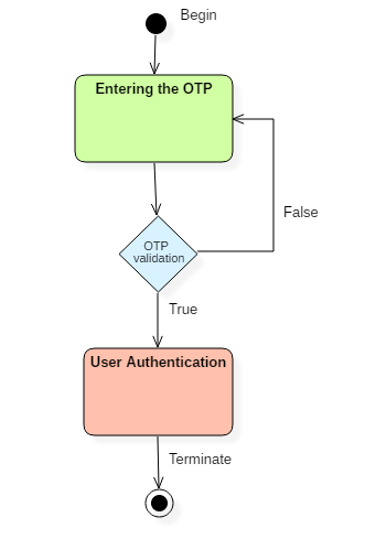
UML State Diagram: A Useful Guide - Edraw - Edrawsoft The focus with this state diagram here is to look into the developments taking place in an authentication process. The first stage is a composite state. Within it, the process has to be completed before you can transit into another state Power off is the final state here. Thus no other development can take place. 2. Edraw Max Installation
Designing Deterministic Finite Automata (Set 8) - GeeksforGeeks
Transition Diagram - Javatpoint A transition diagram or state transition diagram is a directed graph which can be constructed as follows: There is a node for each state in Q, which is represented by the circle. There is a directed edge from node q to node p labeled a if δ(q, a) = p. In the start state, there is an arrow with no source. Accepting states or final states are indicating by a double circle. Some …
What is State Transition Testing? Diagram, Technique, Example
What is Unified Modeling Language (UML)? A state diagram is a type of diagram used in UML to describe the behavior of systems which is based on the concept of state diagrams by David Harel. State diagrams depict the permitted states and transitions as well as the events that effect these transitions. It helps to visualize the entire lifecycle of objects and thus help to provide a better understanding of state-based systems.

State transition diagram for searching for a door. First the ...
› 404We apologize for the inconvenience... - United States ... We recently redesigned State.gov. Many pages are now on our most recent Archive page. Please use our search, browse further via our navigation, or return to the Home page. Still can’t find it? Send us a message using our Contact Us form. A URL is helpful when reporting site problems. Thank you for visiting State.gov.

State Transition Diagram - an overview | ScienceDirect Topics
Compilers Lecture #4 - New York University An input alphabet Σ not containing ε. A transition functionset of next states (or successor states). An element s 0 of S, the start state. A subset F of S, the accepting states (or final states). An NFA is basically a flow chart like the transition diagrams we have already seen. Indeed an NFA (or a DFA, to be formally defined soon) can be ...
State diagram - Wikipedia
What is the Difference Between a Transition State and an ... The reaction diagram above has 2 intermediates and 3 transition states, so it is a 3-step reaction. Finally, the last question you can expect is a question about the shape or a nature of the transition state itself. We know that the transition state is something in-between the reagents and products/intermediate.
All You Need to Know about State Diagrams
Unified Modeling Language (UML) | State Diagrams ... Steps to draw a state diagram - Identify the initial state and the final terminating states. Identify the possible states in which the object can exist (boundary values corresponding to different attributes guide us in identifying different states). Label the events which trigger these transitions. Example - state diagram for an online order -

The state transition diagram for an FSA.. Figure 6 shows the ...
Moore Machine - an overview | ScienceDirect Topics state transition diagram, ... The name of the state (the state identifier) and the outputs for each state are placed within the circle. Each state is referred to as a node. 2. The transition between states uses a line with the arrow end identifying the direction of movement. Each line starts and ends at a node. 3. Each line is accompanied by an identifier that identifies the logical value of ...

State Machine Diagram - UML 2 Tutorial | Sparx Systems
UML State Machine Diagrams - Overview of Graphical Notation State Machine Diagrams. State machine diagram is a behavior diagram which shows discrete behavior of a part of designed system through finite state transitions. State machine diagrams can also be used to express the usage protocol of part of a system. Two kinds of state machines defined in UML 2.4 are . behavioral state machine, and; protocol state machine
Build a DFA to accept Binary strings that starts or ends with ...
alexander-goers.de › rocks-in-a-circle-meaningPage Not Found The diagram presents all the diatonic major and minor keys, in order, based on the amount of sharps or flats. of 11. My next circle was a small one under a rock overhang on a cliff near Black Earth, Wisconsin, which, from 1980-1983, I primarily used for personal The Nabta stone-circle is the only megalithic construction of its kind in all Egypt.
![Solved 1. [4 points] The figure below shows a state | Chegg.com](https://media.cheggcdn.com/media/eb0/eb0cb6ad-55a5-4410-ab61-be2f0fa370a0/phpdyKfh2)
Solved 1. [4 points] The figure below shows a state | Chegg.com
SysML: How to Use State Diagrams to Model Systems Behavior The final state of a state machine diagram is shown as concentric circles. An open-loop state machine represents an object that may terminate before the system terminates, while a closed-loop state machine diagram does not have a final state; if it is the case, then the object lives until the entire system terminates. Example: Events
What is a State Diagram? Definition from WhatIs.com

UML state machine - Wikipedia

State Machine Diagram - UML 2 Tutorial | Sparx Systems

State transition diagram for the XBMC system with the ...

State Transition Diagram - an overview | ScienceDirect Topics
State Machine Diagram in UML | What is Statechart Diagram?

Problem Solving: Finite state machines - Wikibooks, open ...

Partial state-transition diagram containing several ...
![Solved 1. [4 points] The figure below shows a state | Chegg.com](https://media.cheggcdn.com/study/4ea/4ea7b929-43b6-4615-ba89-f091612cc012/image)
Solved 1. [4 points] The figure below shows a state | Chegg.com

State Diagram - an overview | ScienceDirect Topics

UML Diagram Types | Learn About All 14 Types of UML Diagrams

UML state machine - Wikipedia

UML state machine - Wikipedia

State Transition Diagrams - ppt video online download

State Machine Diagram - UML 2 Tutorial | Sparx Systems

What percentage of the transitions in the State Transition ...
State Machine Diagram vs Activity Diagram

State Diagrams A state diagram is a graph whose nodes are states and whose directed arcs are transitions between states. A state diagram specifies the.
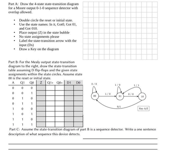
Solved Part A: Draw the 4-state state-transition diagram for ...

State Transition Diagram for User Interface of Thickness ...

Guidelines: Statechart Diagram
0 Response to "43 in a state transition diagram, the circle to the left is the final state."
Post a Comment