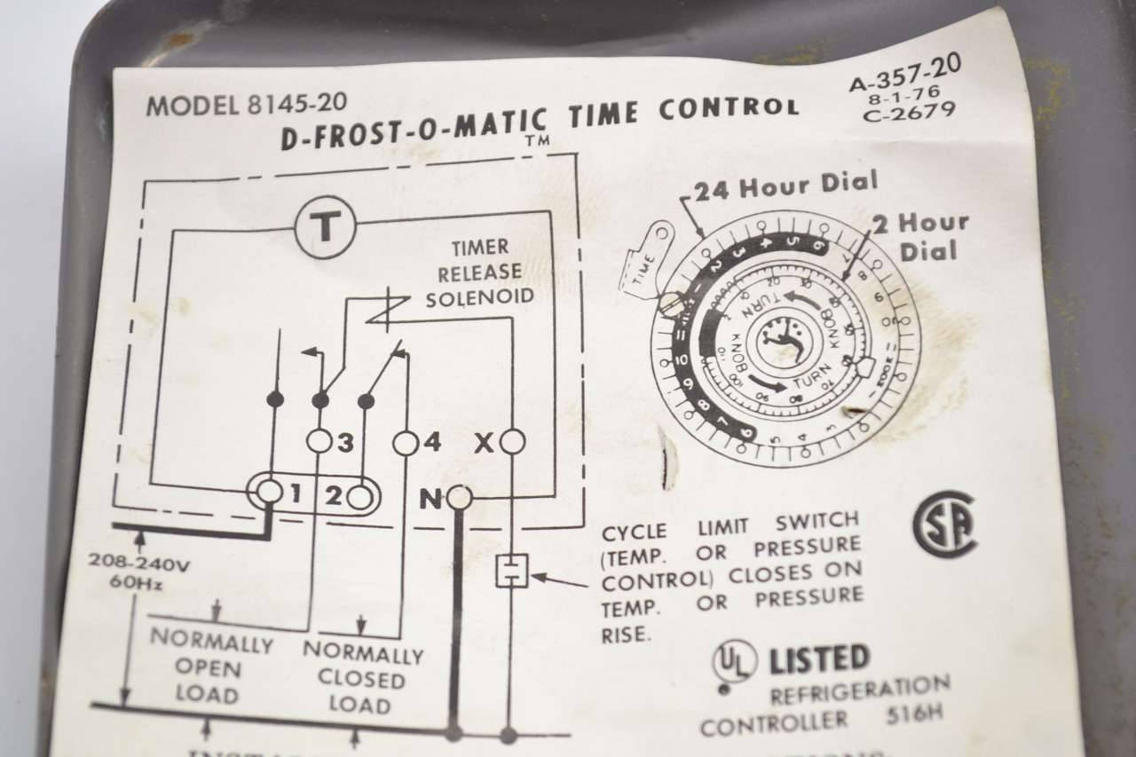
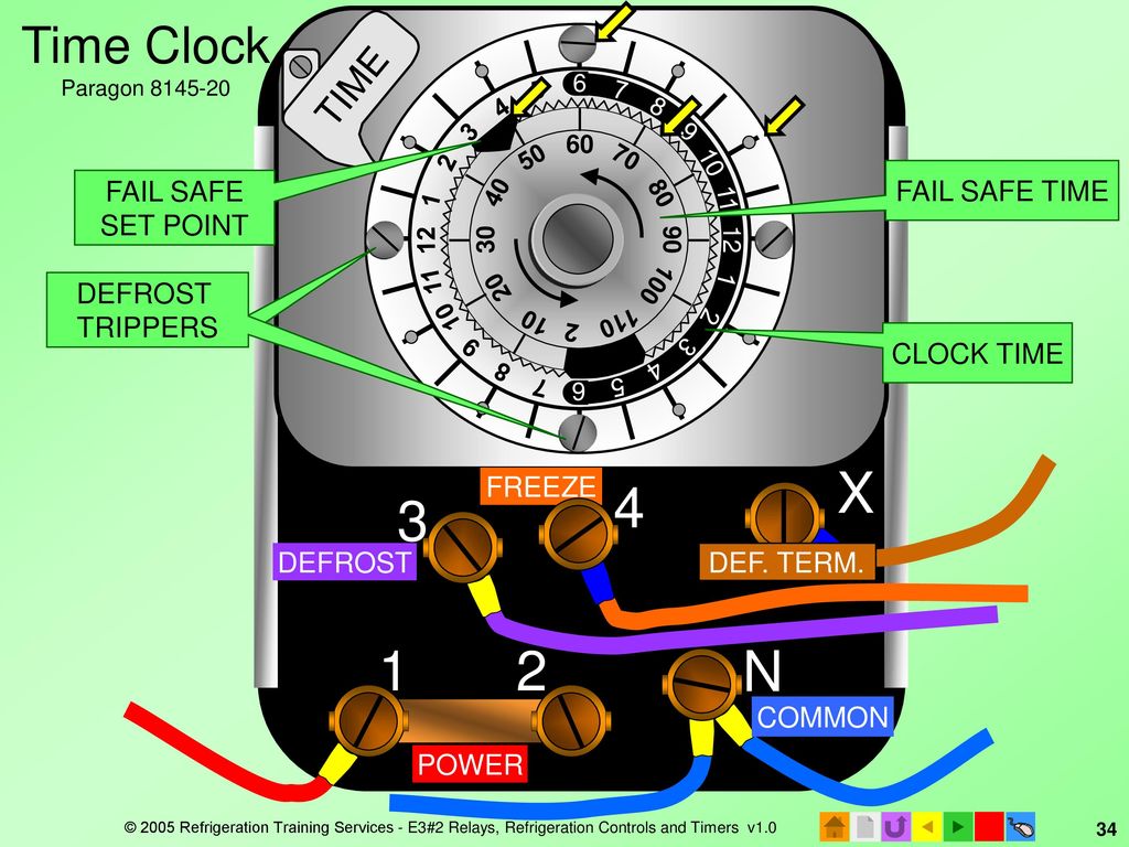
44 paragon defrost timer wiring diagram
Paragon Defrost Timer 8145-00 Wiring Diagram DEFROST. TIMER. Rotate the timer dial clockwise to align the triangle on the inner On the timer wheel, choose a defrost cycle starting time. 2. the wiring diagram chosen. . Robertshaw®, Paragon® and Uni-Line® are trademarks of and Adjustable Defrost Initiation Frequency: One to six times per day. Paragon. Precision. Typical wiring for defrost on a single evaporator freezer ... Wiring for a single evap freezer system or reach in freezer. Any questions or comments Feel free to ask in the comment section . Thanks for watching 👍. ...
PDF Paragon Timers Manual Paragon Timers Manual Paragon electric timers manual. Click here to get file. Paragon 8041, 8045, 8047, 8141, 8143, 8145 with description model numbers and wiring diagrams including paragon 8145 manual defrost timer... Paragon electric timers manual - Google Docs

Paragon defrost timer wiring diagram
PDF 8000 MECHANICAL Series DEFROST TIMER - Everwell Parts 2. Set Defrost Insert pin(s) to desired defrost time(s) on outer dial. 3. Set Defrost Duration Move copper pointer to desired duration of defrost time on inner dial. Install our Commercial Defrost Controls today to understand why Paragon® is Simply the Right Choice™ in Defrost Timers. An ISO 9001 - 2008 Certified Company 1 Year Limited ... Whirlpool Refrigerator Defrost Timer Wiring Diagram ... Paragon Defrost Timer Wiring Diagram. Ge Refrigerator Wiring Diagram Defrost Heater. Whirlpool Refrigerator Wiring Diagram Pdf. Whirlpool Refrigerator Wiring Diagrams. Whirlpool Gold Refrigerator Diagram. Whirlpool Refrigerator Water Line Diagram. 3 Wire Defrost Termination Switch Wiring Diagram. 8 Pin Timer Relay Wiring Diagram. Paragon 8141 00 Wiring Diagram Download - Wiring Diagram ... Dimension: 645 x 471. DOWNLOAD. Wiring Diagram Images Detail: Name: paragon 8141 00 wiring diagram - Paragon Timer Wiring Diagram Diagrams Schematics Throughout Defrost Time Clock 0. File Type: JPG. Source: natebird.me. Size: 193.58 KB. Dimension: 1659 x 891.
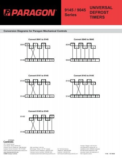
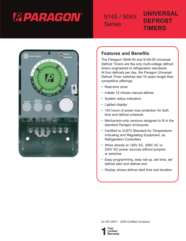
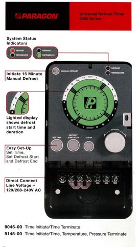
Paragon defrost timer wiring diagram. Paragon 8143 20 Wiring Diagram - schematron.org Paragon 00 Wiring Diagram Timer 20 Somurich 1 On Defrost Image Info File Name: schematron.org Jun 20, · Basically the jumper between 2 and 3 was schematron.org #4 and X were jumpered schematron.org feed was from X to #4,#2 and to the schematron.org the other side one leg to the C/U was broken from #3 to N terminal.I found it schematron.org god ... Paragon 8145 20 Defrost Timer Wiring Diagram - easywiring The paragon series auto voltage defrost timer is designed competitive voltage specific mechanical defrost timers eliminating wiring diagrams. 4 to minutes in s and paragon wiring diagrams electric heat defrosting s s series. Here is a picture gallery about 20 wiring diagram complete with the description of the image please find the image you need. Paragon Defrost Timer 8141 00 Wiring - Wiring Diagrams If not, probably the wiring is backwards. They generally are good timers. If it has, you may have. how to wire model defrost timer - Paragon Defrost Timer Changing the defrost timer will not require use of a wiring diagram. Results 1 - 37 of 37 The Paragon® Series Auto Voltage Defrost Timer is designed for commercial freezers and refrigerators ... PDF 9145 / 9045 UNIVERSAL Series DEFROST TIMERS DEFROST TIMERS An ISO 9001 - 2008 Certified Company Features and Benefits The Paragon® 9045-00 and 9145-00 Universal Defrost Timers are the only multi-voltage defrost timers engineered to refrigeration standards. At four defrosts per day, the Paragon Universal Defrost Timer switches last 16 years longer than competitive offerings. • Real ...
Paragon Defrost Timer 8145 20 Wiring Diagram Find solutions to your paragon defrost timer 20 wiring diagram question. Get free help, tips & support from top experts on paragon defrost timer Adjustable Defrost Cycle Duration: 4 to minutes in S and Paragon Wiring Diagrams Electric Heat Defrosting S & S Series. how to test paragon 20 defrost timer rh waterheatertimer org Paragon 20 Wiring Schematic Paragon Time Clock tors, Paragon ... Paragon Defrost Timer 8141-20 Wiring Diagram The Latest Paragon® Defrost Timer • Universal Defrost Timers (UDT) Universal Defrost Timer - Wiring. Convert to Convert to Convert to N 1 4 32 X. Jun 20, · They are both commercial as well. I know when we draw up the schematic diagram the position of N and X are different. 8145 20 Timer Wiring Diagram Description: Paragon Defrost Timer Wiring Diagram Paragon Defrost Timer Wiring regarding 20 Wiring Diagram, image size X px, and to view image details please click the image. Here is a picture gallery about 20 wiring diagram complete with the description of the image, please find the image you need. Paragon 8145 00 Wiring Diagram - easywiring Paragon defrost timer 8145 20 wiring diagram paragon defrost timer wiring furthermore paragon defrost timer 8145 rh beinclover co. Here is a picture gallery about 20 wiring diagram complete with the description of the image please find the image you need. Wiring diagram sheets detail. Models 8143 00 and 8143 20 wiring.
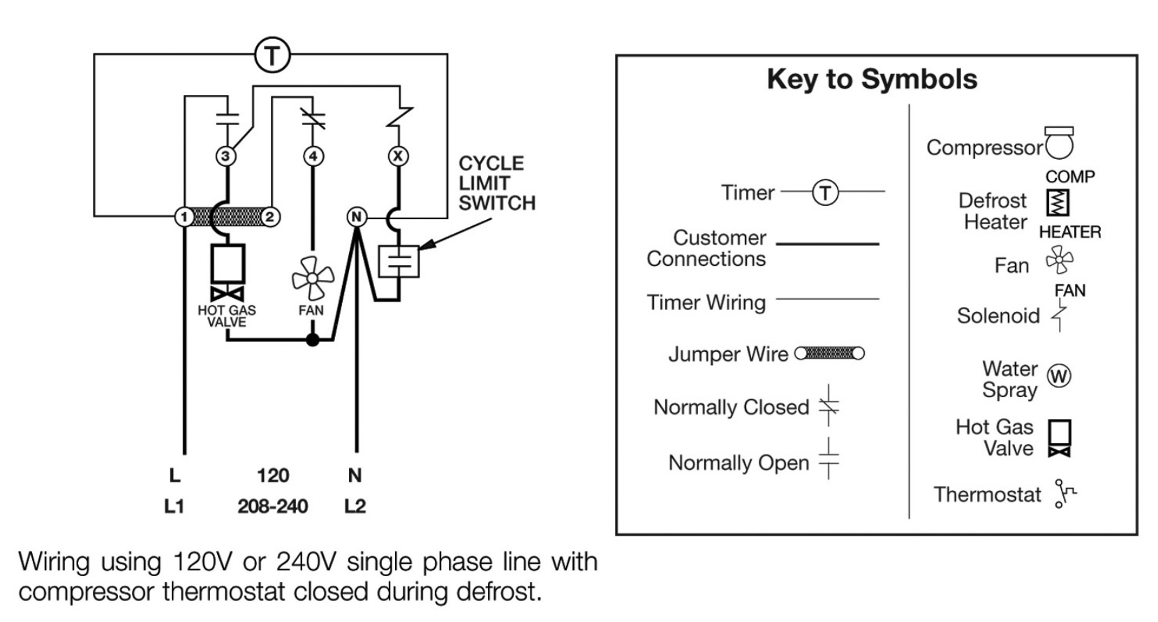
483212 defrost timer wiring - Appliance Repair Forum ... Joined: 11/5/2011 (UTC) Posts: 2. The part replacement for the defrost timer has a black wire that was not on the original part. I have confiremd that this is a replacement but the are options for the black wire depending up the original wiring diagram of the unit. I chose version2/procedure 3 as it seemed to fit. 8145 20 Wiring Diagram - easywiring A diagram showing how to switch wires from. 6 days ago november 22nd i have a paragon 20 defrost timer do you wire the compressor to the timer i cant seem to find a wiring diagram on. Here is a picture gallery about 8145 20 wiring diagram complete with the description of the image please find the image you need. PDF Commercial Refrigeration Defrost Controls - Supco SUPCO Paragon Precision S814100 8141-00 6141-00 ... Normally closed thermostat used with defrost heater. Wiring using 120V or 240V single phase line compressor voltage common to timer. CYCLE LIMIT SWITCH HEATER COMP THERMOSTAT Wiring Diagrams Electric Heat Defrosting S8141 & S8145 Series Wiring Diagrams Electric Heat Defrosting S8041 & S8045 ... Paragon Defrost Timer 8141-20 Wiring Diagram Paragon Defrost Timer 8141-20 Wiring Diagram. Paragon - /V Defrost Timer - Designed for commercial freezers and refrigerators, Paragon commercial defrost controls provide. How to test Paragon defrost timer. Timer dial rotates continuously, and keeps good time. X Trippers are attached to edge of dial. When.
Paragon 8141 00 Wiring Diagram Paragon Defrost Timer 00 Wiring Diagrams -- thanks for visiting our site, this is images about paragon defrost timer 00 wiring diagrams posted by Ella Brouillard in Paragon category on Oct 30, You can also find other images like images wiring diagram, images parts diagram, images replacement parts, images electrical diagram, images repair ...
Paragon Defrost Timer Wiring Diagram - Wiring Systems Paragon defrost timer wiring diagram. Paragon sell sheet shows model numbers and wirings diagrams Replace with TT or CT series. The Paragon defrost and the Tork electric timers. I cant seem to find a wiring diagram on how to wire this correctly Link below has wiring diagrams and wiring. Paragon Defrost Timer 8141-20 Wiring Diagram.
Paragon Timer Wiring Diagram - schematron.org The Paragon® Series Auto Voltage Defrost Timer is designed competitive voltage-specific mechanical defrost timers, eliminating Wiring Diagrams. Simple wiring. Resources: Paragon sell sheet shows model numbers and wirings diagrams, Replace with TT or CT series.
Paragon Defrost Timer Wiring Diagram Wiring Diagrams Paragon Defrost Timer Wiring Diagram On the timer wheel, choose a defrost cycle starting time. 2. Slide the the wiring diagram chosen. . Robertshaw®, Paragon® and Uni-Line® are trademarks of. Defrost Timer Controls. - Series Defrost Typical line voltage wiring diagram. 3. Determine Paragon® Universal Defrost Timer (UDT).
PDF Paragon 8045-20 defrost timer wiring diagram Paragon 8045-20 defrost timer wiring diagram Tap image to zoom. Roll over image to zoom. Paragon 8040 series defrost timer Defrost frequency is one to six cycles per day Adjustable back up defrost termination from 4 - 110 minutes (2 minute increments) Time initiated/time terminated Choice of three contact arrangements for electric heat,
Paragon Defrost Timer Wiring Diagram | vincegray2014 Paragon Defrost Timer Wiring Diagram Free Download 2022 by easter.gleason. Find The BestTemplates at vincegray2014.
Timer Wiring Diagram Manual - Wiring Diagram and Schematic ... Tork Rz307 Timers Digital Lighting Timer Guide Manualzz. Hager Eh 010 Timer Instruction Manual Manualslib. 2510sxt Wiring Diagram Hydrotech Sxt Timer User Manual Page 20 24 Original Mode. Paragon 632 20 Defrost Timer. Eapl Model A1d1 On Power Application Preset Timing Starts And At. Clock Timer Wiring Diagram And Setting Home Appliances Parts ...
Paragon Timer Wiring Diagram For Freezer - Wire Walk in freezer defrost timer wiring diagram wiring diagram is a simplified suitable pictorial representation of an electrical circuit it shows the components of the circuit as simplified shapes and the skill and signal associates together with the devices. Paragon defrost timer wiring diagrams auto electrical wiring diagram.
PDF Paragon Timer Manual Freezer Defrost Timer Live Operation Typical wiring for defrost on a single evaporator freezer Walk in Freezer service call Page 4/38. ... wiring diagrams Page 9/38. Acces PDF Paragon Timer Manualincluding paragon 8145 manual defrost timer... Paragon electric timers manual - Google Docs Download 11 Paragon Timer PDF manuals. User
Paragon 8145 20 Defrost Timer Wiring Diagram on Paragon 8145 20 Defrost Timer Wiring Diagram. Adjustable Defrost Cycle Duration: 4 to minutes in S and Paragon Wiring Diagrams Electric Heat Defrosting S & S Series. tors, Paragon® Commercial Defrost Controls Choice TM in Defrost Timers. SLINE 2.
8141-00 Defrost Timer Wiring Diagram Paragon 00 Wiring Diagram Defrost Timer Circuit Evaporator. The Paragon® Series Auto Voltage Defrost Timer is designed for commercial freezers Wiring Diagrams. AV. AV Heavy-duty steel case with electrical knockouts in the sides, Specifications. Operating Voltages: or / VAC, 60 Hz HEATER. COMP. THERMOSTAT.
Paragon 8141 00 Wiring Diagram Download - Wiring Diagram ... Dimension: 645 x 471. DOWNLOAD. Wiring Diagram Images Detail: Name: paragon 8141 00 wiring diagram - Paragon Timer Wiring Diagram Diagrams Schematics Throughout Defrost Time Clock 0. File Type: JPG. Source: natebird.me. Size: 193.58 KB. Dimension: 1659 x 891.
Whirlpool Refrigerator Defrost Timer Wiring Diagram ... Paragon Defrost Timer Wiring Diagram. Ge Refrigerator Wiring Diagram Defrost Heater. Whirlpool Refrigerator Wiring Diagram Pdf. Whirlpool Refrigerator Wiring Diagrams. Whirlpool Gold Refrigerator Diagram. Whirlpool Refrigerator Water Line Diagram. 3 Wire Defrost Termination Switch Wiring Diagram. 8 Pin Timer Relay Wiring Diagram.
PDF 8000 MECHANICAL Series DEFROST TIMER - Everwell Parts 2. Set Defrost Insert pin(s) to desired defrost time(s) on outer dial. 3. Set Defrost Duration Move copper pointer to desired duration of defrost time on inner dial. Install our Commercial Defrost Controls today to understand why Paragon® is Simply the Right Choice™ in Defrost Timers. An ISO 9001 - 2008 Certified Company 1 Year Limited ...






0 Response to "44 paragon defrost timer wiring diagram"
Post a Comment