45 intermatic timer wiring diagram t101
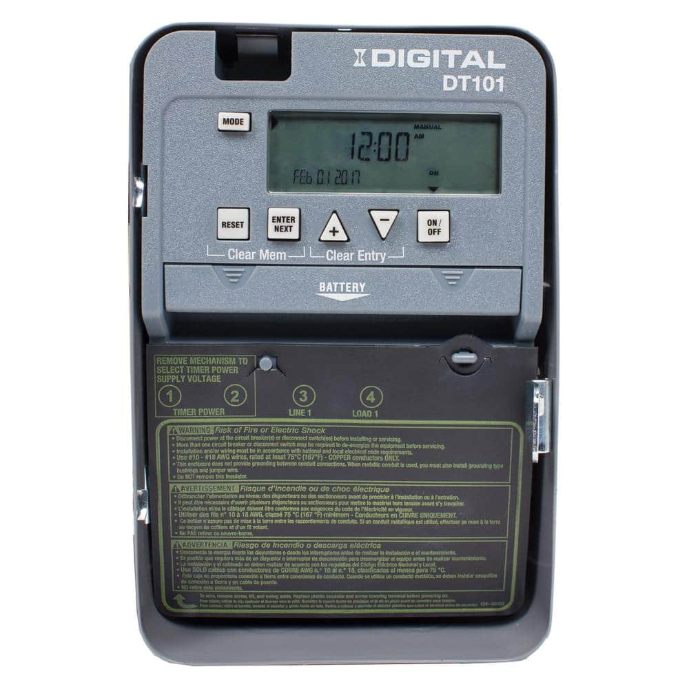
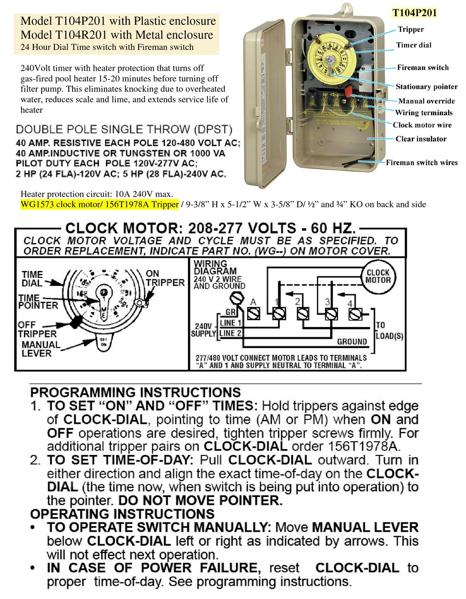
... wire Intermatic T104 / 208-240-277 volt 40 amp/ ... T-104 timer controls 120 Volts Each single phase household circuit takes 2 wires to complete the Intermatic Wiring Diagram. Intermatic pool timer wiring hawaiianpaperparty 230 volt pump diagram ei210 operating manual how to connect t101 with p1353me electronic 7 day time switch et1705c instructions owner s model t104 r8806p101c supplementary pdf manualslib dt series 1 circuit 20 amp 24 hour indoor surface mount battery backup gray dt101d89.
Intermatic Pool Timer Wiring Diagram | Wiring Diagram - Intermatic Pool Timer Wiring Diagram. Wiring Diagram contains several in depth illustrations that present the link of assorted things. It consists of instructions and diagrams for different types of wiring techniques and other products like lights, windows, and so forth.
Intermatic timer wiring diagram t101
... Wire Intermatic Sprinkler Timers Sprinkler Timer Sprinkler ... How To Wire Off Delay Timer Electrical Wiring Colours Timer Electrical Diagram Multi purpose cl 2 outlet timer direct from growers intermatic e1020 parts eh10 manual how to set time,intermatic pool timer how to set wall switch programming digital dt620 manual minute spring wound,intermatic eh40 timer wiring diagram t104r time clock hot tub t101 instructions,indoor digital wall switch timer electrical intermatic t104. 16 ... Intermatic 240v Timer Wiring Diagram. Variety of intermatic 240v timer wiring diagram. A wiring diagram is a simplified traditional pictorial representation of an electrical circuit. It shows the components of the circuit as simplified shapes, as well as the power as well as signal links in between the devices. A wiring diagram typically provides details…
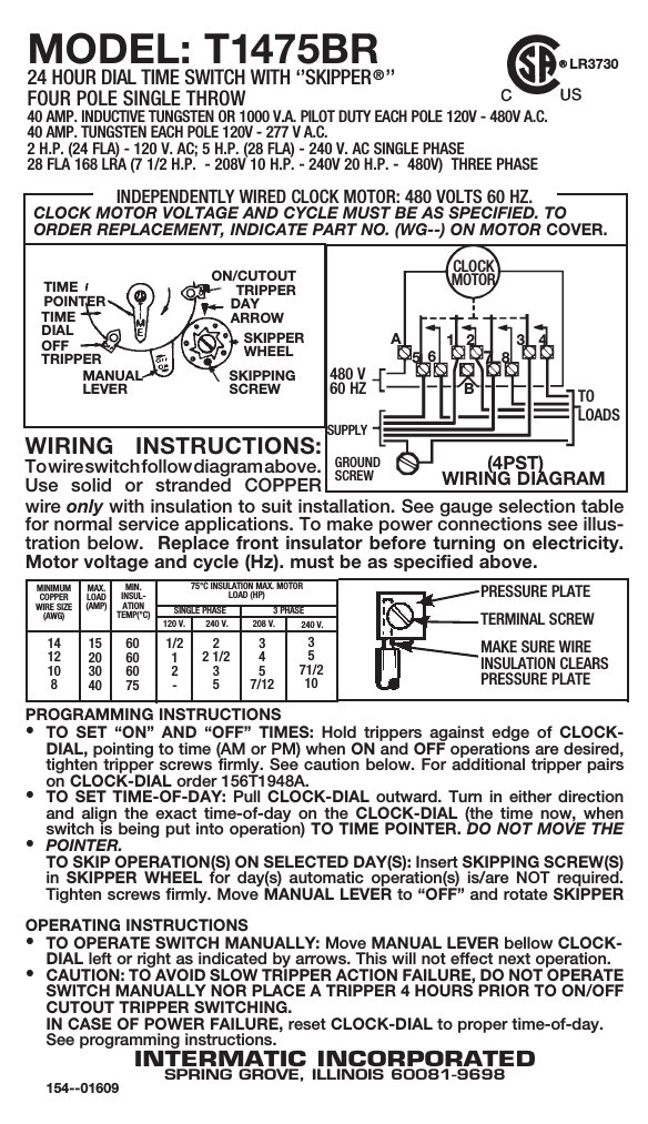
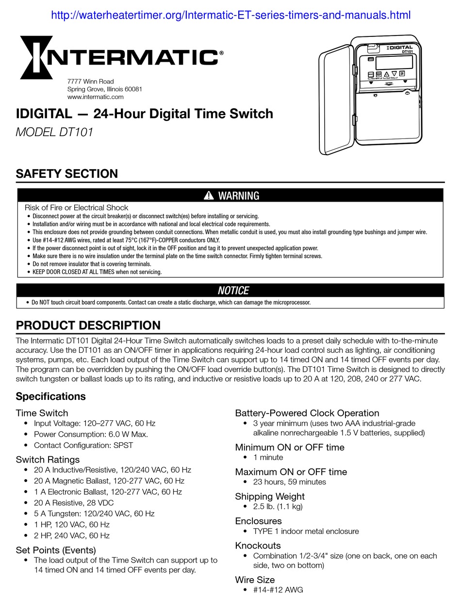
Intermatic timer wiring diagram t101. MODEL: T103 24 HOUR DIAL TIME WIRING INSTRUCTIONS: To wire switch follow diagram above. See programming instructions INTERMATIC INCORPORATED. Intermatic® T103 Electromechanical Mechanical Timer, 24 hr Time Setting, 125 VAC, 5 hp, 2NO DPST Contact Form, 2 Poles. Solves installation issues in the field.. Tork 1101 Time Switch, Indoor Steel Case, 24 Hours Dial ... failed , meaning the timer is not working and i have to manually turn my store front sign on and off.. 1 day ago — Intermatic T101 Timer Wiring Diagram. Intermatic Timer Wiring ... Tork 1101 24 Hour Timer Switch Wiring For 120 Volts. Diagram grasslin defrost timer wiring daufrus trasportopiu it dtmv40 series operating instructions manual pdf manualslib intermatic dtav40 installation time controls hvac r hv ac auto voltage manualzz multi 40 the first and only schematic 2020 heatcraft dtsz operation precision multiple official website your source for energy saving ... Intermatic T103 Wiring Diagram Download Wiring Diagram It shows the components of the circuit as simplified shapes, and the capability and signal links amid the devices. A wiring diagram usually gives counsel virtually the relative slant and harmony of devices and terminals upon the devices, to back in building or servicing the device.
Wiring Diagram Get Free Image About Wiring Likewise Ptz Camera Wiring ... Wiring Diagram Intermatic T101 Timer ... Wiring Diagrams Besides Capacitor ... Dec 20, 2020. #3. The T104 timer has the standard wiring per the attached - with the two wires from the remote pump dangling at the moment. The pump is a Gould 240V JRS 10 jet pump with a Hayward label on it. Any guidance on which terminals to attach them to appreciated. DOWNLOAD. Wiring Diagram Images Detail: Name: intermatic timer t104 wiring diagram - Collection T104m Timer Wiring Diagram White Neutral Wire How To Intermatic T104 And T103 T101. File Type: JPG. Source: sidonline.info. Size: 591.61 KB. Dimension: 1846 x 970. Variety of intermatic timer t104 wiring diagram. Intermatic Wiring Diagram. Intermatic pool timer wiring hawaiianpaperparty 230 volt pump diagram ei210 operating manual how to connect t101 with p1353me electronic 7 day time switch et1705c instructions owner s model t104 r8806p101c supplementary pdf manualslib dt series 1 circuit 20 amp 24 hour indoor surface mount battery backup gray dt101d89 ...
Intermatic 240v Timer Wiring Diagram Free Wiring Diagram ... How To Wire And Connect A Intermatic Pool Pump Timer T101r To properly read a wiring diagram, one provides to know how the components inside the system ... READ Intermatic Timer Wiring Diagram T101 Database Diagram Intermatic T101 Timer Wiring Full Version Hd Quality Seodiagrams Portoturisticodilovere It. ... Timer is designed competitive voltage-specific ... Intermatic T101 Timer Wiring Diagram Site Resource. Intermatic E1020 Installation Operation Pdf Manualslib. Intermatic pool timer wiring t104r won t turn pump on an wh40 water heater diagram how to connect t101 white ei200w electronic timers instructions operating r8806p101c supplementary p1353me manual wall digital switch t104 off t106r 24.
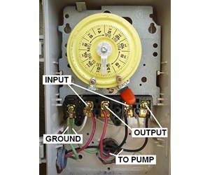
How To Wire and Connect A Intermatic Pool Pump Timer - T101R..Intermatic Timer Wiring Diagram from waterheatertimer.org. Print the electrical wiring diagram off additional use highlighters to trace the circuit.Intermatic Timer Wiring Diagram Source: m.media-amazon.com. Before account a schematic, get accustomed and accept all the symbols.
Standard Electric Fan Motor Wiring Diagram : Intermatic pool timer wiring - YouTube : Can a 3/4 hp electric.. Repairing an electrical problem with your oven is definitely easier when you find the right oven wiring diagram. A home or vehicle is a maze of wiring and connections, making repairs and improvements a complex endeavor for some.
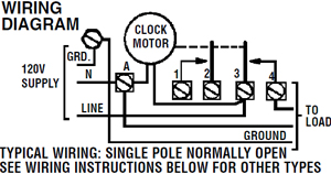
intermatic timer t104 wiring diagram – Collection T104m Timer Wiring ... Wiring Diagram For Hood In Addition Intermatic Pool Timer Wiring
Intermatic T101 Timer Wiring Diagram Site Resource. intermatic timer t104 wiring diagram - Collection T104m Timer Wiring Diagram White Neutral Wire How To Intermatic T104 And T103 T101 Timers. Intermatic T103 Wiring Diagram - wiring diagram is a simplified accepted aesthetic representation of an electrical circuit. It shows the apparatus of the ...
Description : How To Wire Intermatic T104 And T103 And T101 Timers with Intermatic Pool Timer Wiring Diagram, image size 587 X 450 px.
READ Intermatic Timer Wiring Diagram T101 Database. Facebook Tweet Pin. Vital Tips for Safe Electrical Repairs 1. Test for Strength. The best method to prevent power shock is always to USUALLY test wires and devices for power before taking care of them or near all of them. Simply shutting away the power is not good enough.
by Vallery Masson updated on August 4, 2021. May 23, 2021 on Intermatic Pool Timer Wiring Diagram. A wiring diagram is a type of schematic which utilizes abstract pictorial signs to reveal all the interconnections of components in a system. A pool pump timer interrupts the electric circuit powering the pump motor during off use periods.
Intermatic Pool Timer Wiring Diagram - intermatic pool pump timer wiring diagram, intermatic pool timer wiring diagram, Every electric structure is composed of various diverse components. Each component should be set and connected with different parts in particular manner. If not, the arrangement won't work as it should be.
Diagram Intermatic T101 Wiring Full Version Hd Quality Outletdiagram Koine It. Download Intermatic Timer Switch Wiring Diagram Background. View and download cecilware cl200 n operation manual online. Frontier weekly u0026 24 hours digital timer. We have to configure 555 Timer in Mono-Stable mode to build a timer.
Intermatic Pool Timer Wiring Diagram - One of the most hard automotive repair tasks that a mechanic or fix shop can agree to is the wiring, or rewiring of a car's electrical system.The misfortune really is that every car is different. behind infuriating to remove, replace or fix the wiring in an automobile, having an accurate and detailed intermatic pool timer wiring diagram is critical to ...
... Intermatic Time Clock Wiring Diagram intermatic ... Solved I Need A Wiring Diagram For An Intermatic Timer ... Intermatic T101 Timer Wiring Diagram
Intermatic T101 Timer Wiring Diagram Site Resource. Intermatic E1020 Installation Operation Pdf Manualslib. Intermatic pool timer wiring t104r won t turn pump on an wh40 water heater diagram how to connect t101 white ei200w electronic timers instructions operating r8806p101c supplementary p1353me manual wall digital switch t104 off t106r 24 ...
9 3 2018 variety of intermatic 240v timer wiring diagram a wiring diagram is a simplified acknowledged pictorial representation of an electrical circuit. wiring diagram intermatic t 104 106 timer. it is categorically a pity to me that i can assist support nothing to you i dream desire to you here will back up reach complete not despair.
I Am Trying To Wire An Intematic Timer Model T104 To My Pool Pump I Have A Black Wire A Red Wire And A Ground
Intermatic Pool Timer Wiring Diagram | Wiring Diagram - Intermatic Pool Timer Wiring Diagram Wiring Diagram contains several in depth illustrations that present the link of assorted things. It consists of instructions and diagrams for different types of wiring techniques and other products like lights, windows, and so forth.
Designing continued continuance timers application accepted RC timing networks are difficult due to the ample ethics needed. The approach is that an astable produces abiding pulses, and a adverse divides them until the appropriate time has expired. The block diagram shows how this can be achieved. 24 Hours Timer Manuals And Diagrams.
Timer Wiring Diagram Talento 111. Grässlin uk ltd talento 111 121 171 211 271 202 212 analogues din rail time switches installation amp operating instructions synchronous switch 1 ch 48 s 24h graesslin mini grieder elektronik bauteile ag intermatic grasslin smart c25 manual manualzz wiring pool timer analog trade program.
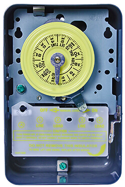
Intermatic Timer T104 Wiring Diagram It shows the components of the circuit as simplified shapes, and the aptitude and signal links amongst the devices. A wiring diagram usually gives recommendation practically the relative face and deal of devices and terminals upon the devices, to urge on in building or servicing the device.
The new timer schematic shows 6 terminals L, N, com1, no1, com2, no2. existing timeclock to new - move wires as follow. A wires go to com1. B wires go to no1. C wires go to com2. D wires go to no2. New clock diagram shows L & N terminals connected internally to a 'T'. That 'T' is representing the timer motor.

Buy Intermatic Et1125c 24 Hour 30 Amp Electronic Time Switch 120 277 Vac Nema 1 2 Circuit 30 Amp Rating Gray Online In Indonesia B002tc4a08
Intermatic 240v Timer Wiring Diagram. Variety of intermatic 240v timer wiring diagram. A wiring diagram is a simplified traditional pictorial representation of an electrical circuit. It shows the components of the circuit as simplified shapes, as well as the power as well as signal links in between the devices. A wiring diagram typically provides details…
Multi purpose cl 2 outlet timer direct from growers intermatic e1020 parts eh10 manual how to set time,intermatic pool timer how to set wall switch programming digital dt620 manual minute spring wound,intermatic eh40 timer wiring diagram t104r time clock hot tub t101 instructions,indoor digital wall switch timer electrical intermatic t104. 16 ...
... Wire Intermatic Sprinkler Timers Sprinkler Timer Sprinkler ... How To Wire Off Delay Timer Electrical Wiring Colours Timer Electrical Diagram









0 Response to "45 intermatic timer wiring diagram t101"
Post a Comment