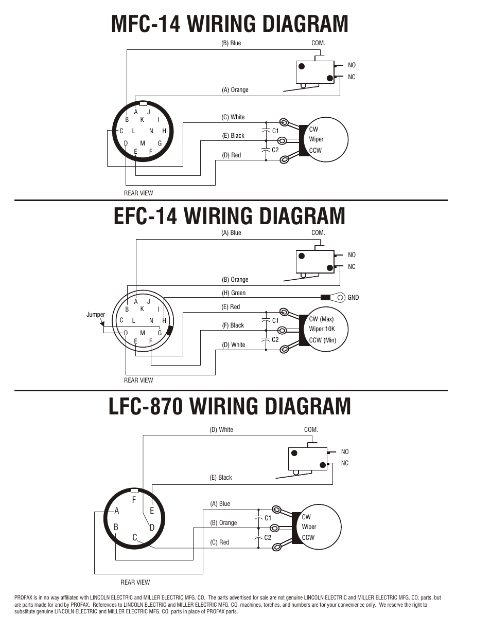
44 miller 14 pin connector wiring diagram
I have the wiring diagram for the Intelliweld. I was going to try to hook a 14 pin up to it as well. You can buy the cable to adapt the sm 1 to a 10 pin connector from miller4less, but I figure why pay $60 if I have the 10 pin connectors. I could just wire the 10 pin to the sm 1 without too much trouble. Manuals & Parts.
I have found a few ID's on the older Mercs to run a cluster. The pin outs on this page are associated with the CANopen protocol. 0b. The protocol was officially released by the SAE in 1986. I found both (CAN high & low) on the pink and white wires at the connector, so the connector is connected to the BCM and the bus.
miller® style rear connector Wire Size Length Part No. Stock No. Amp Knucklehead Conductor Tube .045" (1,2mm) 15 ft. (5M) WM250M-15-4045K4 1027-1061 250 62SFLX480 (Stock No. 1620-1106)

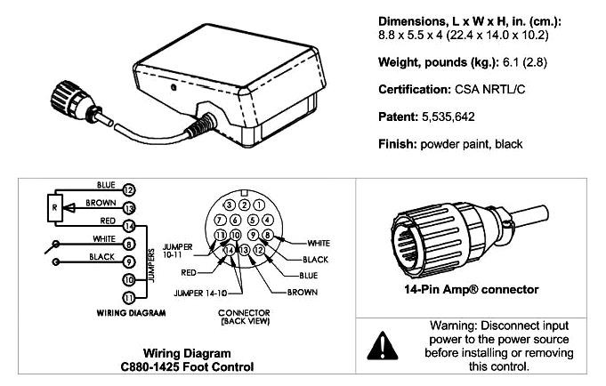
Miller 14 pin connector wiring diagram
I am trying to add a blade attachment to my John Deere 320E. I bought the kit for the JD, but I need two connectors so I can attach the blade wiring.. I need a 14 pin round female and a 3 pin round male. Do you have a part number for the 3 pin. PLEASE CLICK HERE. Hello Do you have a wiring diagram for a female 14 wire plug on a cat broom?
Arc-Zone.com Miller® Style 14 Pin Male Plug [MIL-136961] - MIL-136961 Miller® Style 14 Pin Connector, Male Plug with 14 Pins.
Inserting a pin in a HD36-18-14SN-059 14 pin PLUG (attachment side) ASM LADD AUX
Miller 14 pin connector wiring diagram.
Miller 14 Pin Connector Wiring Diagram - wiring diagram is a simplified normal pictorial representation of an electrical circuit. It shows the components of the circuit as simplified shapes, and the capability and signal associates along with the devices. A wiring diagram usually gives opinion practically the relative point of view and deal ...
Thanks! I have the wiring diagram for the Intelliweld. I was going to try to hook a 14 pin up to it as well. You can buy the cable to adapt the sm 1 to a 10 pin connector from miller4less, but I figure why pay $60 if I have the 10 pin connectors. I could just wire the 10 pin to the sm 1 without too much trouble.
Dec 08, 2021 · Hi, does anyone have a wiring diagram for lexmoto assault efi 2019, the ignition switch they sell on cmpo doesn't fit to wiring loom on bike:))). They is a 6 pin plug with red, black and brown on bike and an 6 pin plug with red, black, green, black/white on ignition switch all of them in completely different positions. Guess what, bike doesn't ...
Rocker 14 Pin 129337 Rotary East-West 14 Pin 151086 Push Button 2-Button 14 Pin 300666
* - Main goods are marked with red color . Services of language translation the ... An announcement must be commercial character Goods and services advancement through P.O.Box sys
I have the wiring diagrams for the Miller 14 pin and the T/A 10-4015 and10-4016 foot controler I could e-mail you. When I did mine it wasa different model T/A foot control from the 10-4015 so I had to remove the cover and use a ohm meter to convert it to the Miller 14 pin.
Miller 14 Pin Connector Wiring Diagram Free Wiring Diagram These days, there are several sources that attempt to allow Miller Remote Wiring Diagram to the mechanic online. Most time these providers have either incomplete or wrong diagrams that can potentially cost the shop wasted time, keep or even possibly a lawsuit.
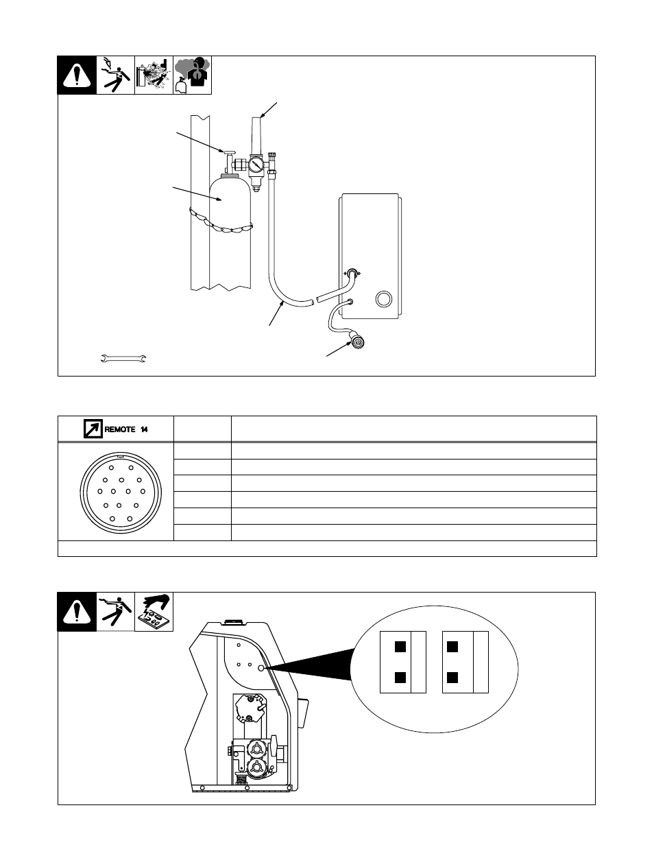
MILLER STYLE 14 PIN RECEPTACLE DIAGRAM. HOW TO IDENTIFY THE 14 PIN CONNECTOR ON YOUR MACHINE. 1. With the machine turned on (the cooling fan may or may not run with the machine "on"). Normally of the machine has a pilot light that lights when the machine is "ON". 2. With a meter on AC Voltage check between pins A & B.
C810-1425 TIG Foot Pedal for Miller RFCS-14 (043554) with 14-Pin Plug. This TIG foot control cross reference guide will help you determine which foot pedal can be used with your welder. To determine which control will work with your welder, check the number of pins on your welder's remote receptacle (and the shape of the connector) to make sure ...
Miller 300430 Wireless Hand Control and 14-Pin Receiver. 4.5 out of 5 stars. (3) 3 product ratings - Miller 300430 Wireless Hand Control and 14-Pin Receiver. $800.00. $10.00 shipping. 5 watching.
DC400 (codes with 14 pin amphenol) B. INDIRECT CONNECTION K963 6 P A K963 K864 14 P A K963 a K864 Aa. POWER SOURCE DC250 DC400 (older codes with termi-nal strip) K843 K963 Ta S K963 a K843 Aa. 1 * Disconnect ground lead at connector end of K963 when used with V250S. See CONNECTION OF THE AMPTROL TO THE POWER SOURCEin this manual for details.
MUYI 10 Kit 2 Pin Way Waterproof Electrical Connector 2.5mm Series Terminals Quick Locking Wire Harness Sockets 4.4 out of 5 stars 1,632 $10.99 $ 10 . 99 $14.99 $14.99
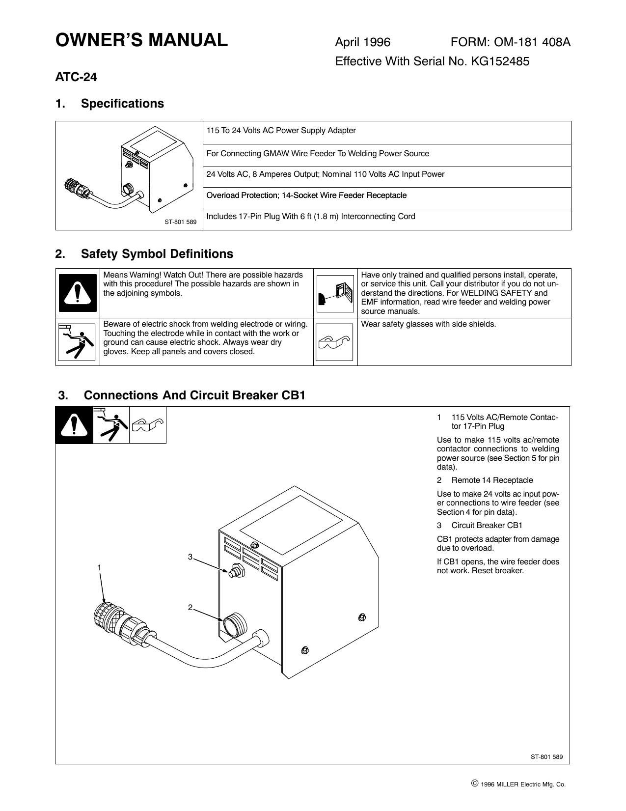
Wiring Diagram April 24, 2020. Miller 14 Pin Connector Wiring Diagram Bobcat 7 Pin Diagram Wiring Diagram Show is one of the pictures that are related to the picture before in the collection gallery, uploaded by autocardesign.org. You can also look for some pictures that related to Wiring Diagram by scroll down to collection on below this picture.
I think all you need to do is order the 14-pin connector from Miller or re-use an old one and connect the wires to the correct pins. If the wires are soldered to the pins in the old connector, you should be able to remove the soldered pins from the old connector, remove the correct pins on the 14-pin connector and push the pins in their correct locations.
Miller. Millermatic plus 30A Spoolgun(Canada) This the wiring diagram to convert the 30A 8 wires 10 pin connector plug to fit the MTSS. Does anyone have the actual wiring diagram for a Miller 30A spool gun? Ive had one for a few years, a Ya!BUDDY!! score at Reliable Tools. Could be the welder, the gun motor, the wiring, ect.
Miller 14 Pin Connector Wiring Diagram Free Wiring Diagram. Miller Remote Wiring Diagram - wiring diagram is a simplified suitable pictorial representation of an electrical circuit. It shows the components of the circuit as simplified shapes, and the facility and signal associates between the devices.
Tig Torch Parts Diagram. Schematic illustration of welding processes: (a) P-TIG and (b) P-LBW ... [FE_6475] Power Inverter Circuit Diagram Moreover Tig Inverter Welder ... switch mode power supply - Understanding SMPS with UC3845 - Electrical ... miller 14 pin info page.
Miller 14 Pin Wiring Diagram images, similar and related articles aggregated throughout the Internet.
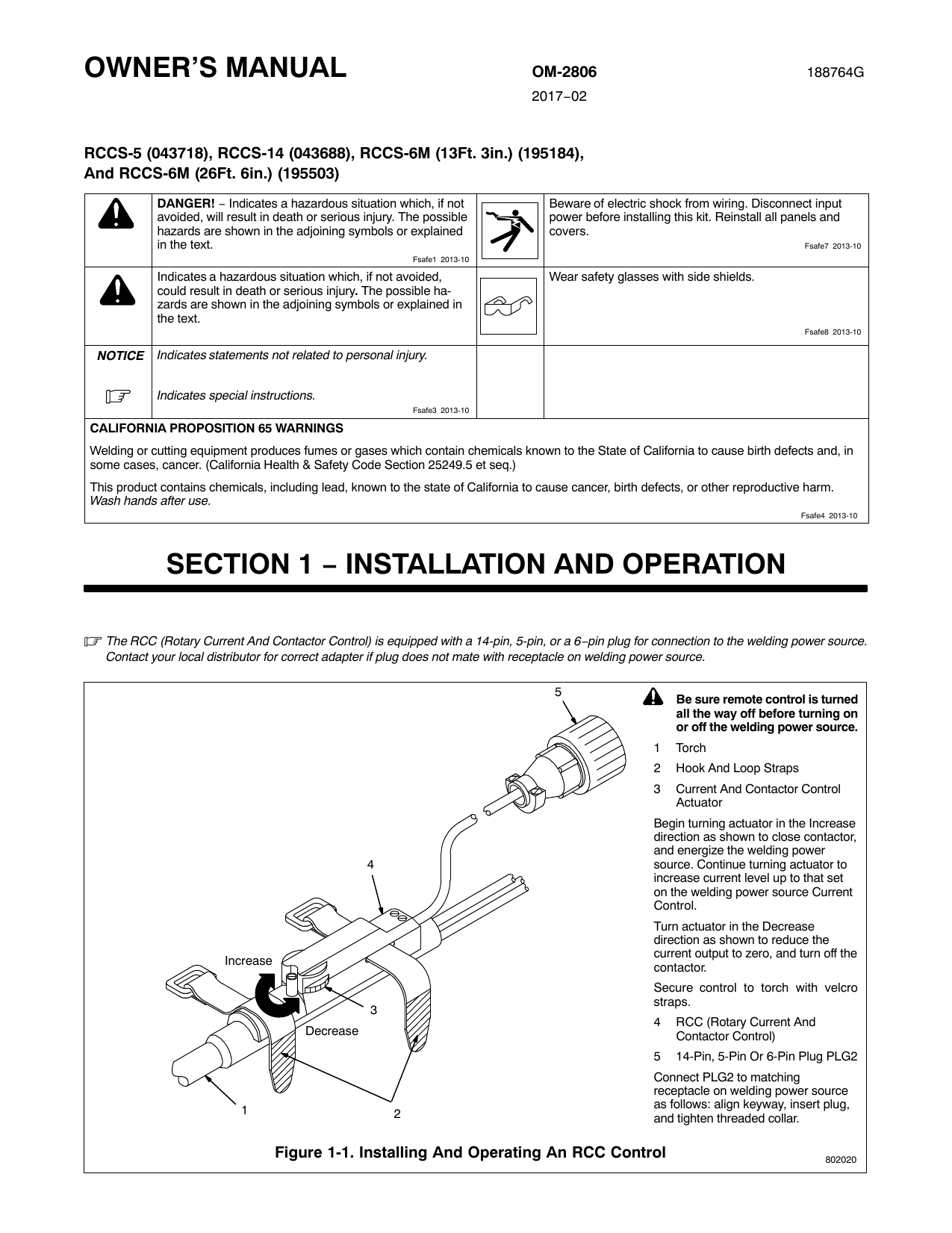
the 14-pin receptacle of Miller machine. 90-foot (27.4 m) operating range. Wireless Remote Hand Control* #300 430 For remote current and contactor control. Receiver plugs directly into the 14-pin receptacle of Miller machine. 300-foot (91.4 m) operating range. Extension Cables for 14-Pin Remote Controls #242 208 025 25 ft. (7.6 m) #242 208 050 ...
Has the LN-7 (115 VAC) 6-pin female plug at one end and a 14-pin (115 VAC) Miller plug on the other end of a 5- conductor cable. JAC-LN9-M14x Feet . Has the LN-8, LN-9, NA-3, NA-4, NA-5 or NA-5R 9-pin female plug at one end and a 14-pin Miller plug at the other end of a 9- conductor cable. JAC-L14-M14
14 pin connector. 08-19-2010, 05:12 PM. I am trying to figure out what to use for a gas valve on my little miller inverter cst280. I have had it for about a year now, and I just emptied my third bottle of argon to atmosphere because I was stupid enough to forget to turn off the valve on the tig torch head... My question: is there an output on ...
So, if you desire to have all of these great images related to (Best Of Miller 14 Pin Connector Wiring Diagram. ), click save link to save these graphics to your laptop. There're all set for down load, if you'd prefer and want to obtain it, simply click save logo in the page, and it will be directly downloaded in your home computer.












0 Response to "44 miller 14 pin connector wiring diagram"
Post a Comment