44 torque diagram for shaft
The turbine is connected to the output shaft of the torque converter. Its twisting power (torque) is geared to the rear wheels of the tractor. The torque converter takes low torque at high speeds and converts it to high torque at low speeds. Component # 3. Differential Unit and Final Drive: Differential Unit: We obtain the free body diagram of the part of the shaft, by passing a plane perpendicular to the shaft at any point between A and B. So we have Σ M x= 0, this implies T AB= 35N-m. The conclusion reached is that resisting torque developed between shaft A and B is 35N-m Strength of Materials Prof. M. S. Sivakumar
Let us see how to calculate the shaft diameter if the shaft is subjected to bending. 2. Calculating Shaft Diameter under Bending Moment only (Axle Shafts) Fig: Shaft Subjected to bending Similar to the torsion Equation, we have a bending equation, Where M = Bending Moment I = Moment of inertia of the shaft σ b = Bending stress

Torque diagram for shaft
Samman LED Ditch Light Mount LED Pods Light Hood Hinge Mounting Bracket Compatible with Toyota Tacoma 2016-2020. $15.99. Pangburns Millionaire$ Candy, 9.75 Ounce Box, Pangburn's Millionaires Candy, Buttery Pecans, Creamy Caramel, Honey, and Mouthwatering Milk Chocolate; Texas Born, and Loved by All. $17.39. Shaft torsion - problems with sum (4) and torque diagram Options Previous Topic Next Topic Wanna join the discussion?! Login to your SMath Studio Forum forum account or Register a new forum account. Users browsing this topic SMath Studio Forum » SMath Studio » Questions » Shaft torsion - problems with sum (4) and torque diagram Forum Jump The propeller shaft is a component that transmits mechanical torque, rotation, and power. Driveshafts, driving shafts, tail shafts, and Cardan shafts are all names for these shafts. The driveshaft is used to transfer torque between components that are not directly connected due to distance or the need for relative motion.
Torque diagram for shaft. The formula for frictional torque can be approximated for angular contact bearings to: T (fr) = 0.5 * μ * radial load (N) * bearing bore (m) μ = 0.002 for angular contact ball bearings (this is low because there is lubrication and non-contact seals) so the frictional force in reality acting between shaft and the lubricant Torque Of The Shaft Simply put, the resistance of the shaft to twist around its own axis when a force is applied to the clubhead (see diagram). Manufacturers apply a set force to a clubhead and the resulting rotation is measured in degrees. Use our part lists, interactive diagrams, accessories and expert repair advice to make your repairs easy. Honda engines offers a full line of small 4-stroke engines. Gross torque/12.5n.m/2,800rpm engine torque, this 500-hour engine provides enough power to run a wide range of equipment, including log splitters and pressure washers. The torque, T Nm , required to rotate shafts of different diameters, D mm, on a machine has been tested and recorded as below. D (mm) 6 10 14 18 21 25 T (mm) 5.5 7 9.5 12.5 13.5 16.5 a) Plot a scatter diagram of the results with diameter of the machine as the independent variable.
What Is An Alta Cb Shaft? Alta CB Soft Regular weighs in at 66 grams graphite. It is our lightest and most flexible shaft. It can also be classified as a mid/high-launching shaft and mid/high spin shaft. True Temper's lightweight steel shaft XP 95 is engineered to deliver a strong launch angle, and high ball fight. Torque definition, something that produces or tends to produce torsion or rotation; the moment of a force or system of forces tending to cause rotation. See more. Figure 3-2 Diagram of gear’s torque transmission calculation. As you can see from Figure 3-2, by reducing the output shaft speed from the input shaft by 1/2, the output torque increases by a factor of 2. 4. Consideration of machine efficiency. As shown in the previous chapter, you can calculate a gear’s number of rotations by the number of ... This paper aims to investigate a method for real-time and continuous dynamic torque monitoring of high-speed rotating shafts. By analyzing different existing sensors and measurement methods, a capacitive grid sensor based on dynamic angular displacement detection is proposed. The sensor has a soft membrane shape and is easy to install or disassemble on the rotating shaft. Its mass is very ...
1. Calculate the smallest safe shaft diameter for the shaft 1 and 2. Provide a free body diagram and all necessary bending moments and torque diagrams. 2. Calculate the dimensions of the keys and the keyways at shaft 1 and 2 for the two gears and the pulleys. 3. Determine the critical speed of rotating shaft 2. B. DRAWINGS AND ASSEMBLY 1. In physics and mechanics, torque is the rotational equivalent of linear force. It is also referred to as the moment, moment of force, rotational force or turning effect, depending on the field of study.It represents the capability of a force to produce change in the rotational motion of the body. The concept originated with the studies by Archimedes of the usage of levers. It is consists of bearings that rotate two axle shafts. 3. Pinion Shaft or Cross Pin These are two pinion gears and their supporting shaft is called the pinion shaft. It is fitted in the differential case. 4. Axle Shafts or Half Shafts The pinion shaft meshes with two differential side gears connected to the inner ends of the axle shafts. 5. The speed-torque diagrams are presented below. These diagrams clearly demonstrate a speed reduction of 2 to 3% as the torque changes from no-load to full load. In DC motors, the armature MMF reacts to the field MMF. This behavior is introduced as the armature reaction.
A solid 0.75-in.-diameter shaft is subjected to the torques ...
Assume that the gear train is placed between the servomotor and the drive shaft of the 24-inch-long forearm with the 55-lb load as shown in the diagram …
STRESSES IN SHAFTS DUE TO SHEAR FORCES AND BENDING MOMENTS ...
A single phase motor has usually fix speed and is very limit in speed regulate. Good way is use a gearbox + spindle. This is cheap solution. 2 phase motor -> dosen't exist on earth. In case of using VFD, do you need 3 phase motor. The 2.2 KW + ER20 Huanyang VFD + spindle set have 24000 rpm.

Create Torque Diagram for Pulley Shaft Design
Torque transducers based on strain measurement are normally made by applying strain gauges to a shaft to measure the shear strain caused by torsion. The shear stress causes strains to appear at 45° to the longitudinal axis of the shaft. So, the strain gauges must be placed precisely at 45° to the shaft axis as shown in fig.
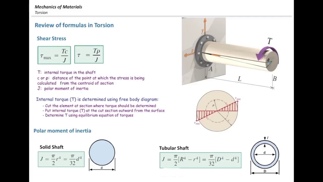
Torsion of Shafts
Shaft Torque or Useful Torque T sh is the actual torque available at the shaft, so T sh = Gross torque and T g = Torque lost due to the friction and windage losses. Now, a revolving magnetic field rotates at a speed of Ns rpm to provide input to the rotor through the air gap. In terms of gross torque Tg and speed, the rotor input can be written as,
Torque calculations: Rotating vertical shaft | Physics Forums
How to calculate the shaft diameter from the torque? How to calculate Shaft Diameter under Twisting, Bending Moment, and Fluctuating? How […] Filed Under: Machine Design Tagged With: how to calculate shaft diamter, how to draw bending moment diagram for shaft, how to find resultant force. Join our mailing list. Leave this field empty if you ...

A solid 0.75-in.-diameter shaft is subjected to the torques ...
Sep 06, 2021 · The propeller shaft is a component used for transmitting mechanical power, torque, and rotation. These shafts as also known as driveshaft, driving shaft, tail shaft, or Cardan shaft. The driveshaft is used to transfer torque between components that cannot be connected directly because of distance or the need to allow relative motion between them.

Space diagram, torque, loads and bending moment acting on the ...
Fig. 4: Block diagram of closed-loop drive for a stepper motor. Stepper Motor Characteristics. Figure 5 shows the characteristics of torque stepping rate. As the stepping rate is increased, the motor can provide less torque because the rotor has less time to drive the load from one position to the next position.
D.C. Motor Torque/Speed Curve Tutorial:::Understanding Motor ...
It is recommended that a torque diagram be prepared. Determine the forces that are exerted on the shaft, both radially and axially. Resolve the radial forces into components in perpendicular directions, usually vertically and horizontally. Solve for the reactions on all support bearings in each plane.

Flywheel and Shaft Torque Analysis | Engineering Reference ...
Gear ratios, such as 12:21, are a measurement of the difference between the number of teeth in the crankshaft gears and the prop shaft gear. Covers complete tear down and rebuild, pictures and part diagrams, torque specs, maintenance, troubleshooting, etc. Evinrude Scout Trolling Motor For Sale.

The solid 50 mm diameter shaft is used to transmit the torque ...
Calculate the smallest safe shaft diameter for the shaft 1 and 2. Provide a free body diagram and all necessary bending moments and torque diagrams. 2. Calculate the dimensions of the keys and the keyways at shaft 1 and 2 for the two gears and the pulleys. 3. Determine the critical speed of rotating shaf t 2.

Solved) - Concentrated Torques on a Steel Shaft Consider the ...
Koenigsegg is continuing its in-house technology development and advanced electromobility component offerings. It started with David, the recently introduced 6-phase inverter, followed by the company's newest innovation, the Quark electric motor that utilizes a novel torque/power-rich balance between radial (power-dense) and axial (torque-dense) flux topology dubbed Raxial Flux.

File:Torque shaft diagram.gif - Wikimedia Commons
In this topic, you study Induction Generator - Construction, Diagram, Torque Slip Characteristics, Advantages & Applications. If the terminals of the stator winding of a three-phase induction motor are kept connected to a three-phase supply of constant voltage and frequency, and at the same time, it is driven at a speed higher than the synchronous speed with the help of a suitable prime ...
Drive Shafts - Roy Mech
Answer to: Draw the torque diagram fot the shaft shown below. If the tubular shaft is made from material having an allowable shear stress of...1 answer · Top answer: Given Data • The allowable shear stress is: τallow=85MPaτallow=85MPa. • The shaft diameter is: {eq}{d_o} =...

Synthetic bending force diagram and torque diagram of shaft C ...
It is fitted over the ends of the two shafts utilizing a gib head key, as shown in Fig. The power is transmitted from one shaft to the other shaft utilizing a key and a sleeve. It is, therefore, necessary that all the elements must be strong enough to transmit the torque.

How to Draw a Torque Diagram Without Equations
torque converter diagram How a torque converter differs from a gearbox? A torque converter is a device that performs a function similar to that of a gearbox, i.e. to increase the torque while reducing the speed. ... As the turbine rotates the input shaft of the transmission also rotates and made the vehicle to move. The turbine is also has a ...

TORSION CO 2 ABILITY TO ANALYZE TORQUELOADED MEMBER
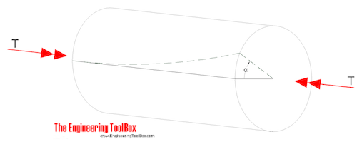
Torque Diagram and Torsional Stress of Circular Section. Torsional or twisting moment is caused by forces whose resultant does not pass through the axis of rotation (called the shear center) of the structural member. Typically, significant torsions are induced in shafts of rotating motors, structural members subjected to eccentric loading (e.g., edge beams) or curved in the horizontal plane (e.g., curved bridges, helical stairs).
Mechanics Map - Axial Force Diagrams and Torque Diagrams
TORQUE: TORQUE: LUBE: INCRE. 301 Engine: 350-455 : Bolt, main bearing cap to block 70 lb-ft 100 lb-ft oil 20 lb-ft Bolt, rear main cap to block 100 120 oil 20 Bolt, cylinder head 85 95 * oil 20 Bolt, flywheel to crankshaft 95 95 dry 40 Bolt, oil pan to block 12 12

Shaft Torque - an overview | ScienceDirect Topics
Consider the steel shaft subjected to the concentrated torques shown. This shaft is made from A36 steel and has a diameter of 20 mm. The shaft is securely fixed at point A. (a) Determine the internal torque of BC, CD, and DA (b) What is the maximum...

Torsion Of Circular Shafts. - Civil Engineering Portal
They are also used in serving misalignment between equipment shafts. Diaphragm couplings transmit torque from the outside to inside diameter and vise versa. They use a single or a series of plates for the flexible members and allows angular, axial, or parallel misalignment. Diaphragm couplings are used when high torque and high speed are required.

What is a Drive Shaft? | How does a Drive Shaft work ...
The 4l60e torque converter is designed to lock up primarily in 4th gear (can also be enabled to lock up in 3rd gear as well), so when it doesn't lock, it's quite noticeable. When a converter locks, it lowers the RPMs and usually feels like going into another gear. When it doesn't lock however, RPMs will keep climbing in 4th gear.
Section I.1
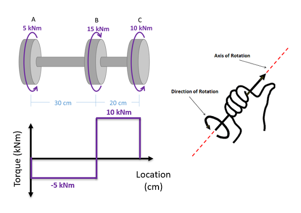
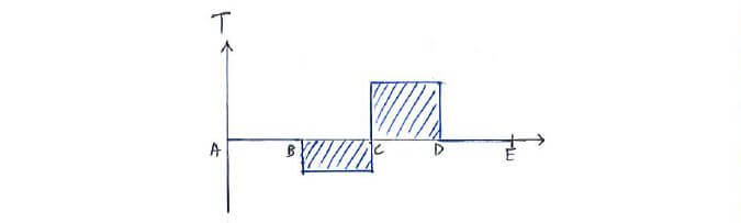
To create the torque diagram for a shaft, we will use the following process. Solve for all external moments acting on the shaft. Draw out a free body diagram of the shaft horizontally, rotating the shaft if necessary, so that all torques act around the horizontal axis. Lined up below the free body diagram, draw a set of axes.

Torque and angle of rotation in linked shafts – GeoGebra
Aug 15, 2007 — Find torsional and bending stresses in shaft. Example Problem 17-1: Design Stresses in Shafts. August 15, 2007. 23. • Find the torsion in ...7 pages
Torsional stress part2, Free body diagram and examples
A torque wrench is a tool used to apply a specific torque to a fastener such as a nut, bolt, or lag screw.It is usually in the form of a socket wrench with special internal mechanisms.. A torque wrench is used where the tightness of screws and bolts is crucial. It allows the operator to set the torque applied to the fastener so it can be matched to the specifications for a particular …

Machine Components: Shafts, Keys, and Couplings Pages 1 - 12 ...
May 29, 2012 · Draw Torque Diagram in Six Steps. The torque diagram of a shaft is analogues to the shear force and bending moment diagram of a beam. It is an important engineering diagram from the pulley shaft design point of view. The steps required to draw it will be discussed with the help of the following example:
![Axi Symmetric Shafts in Torsion - [PDF Document]](https://demo.fdocuments.in/img/378x509/reader024/reader/2021012006/5695d3181a28ab9b029cd1e4/r-2.jpg)
Axi Symmetric Shafts in Torsion - [PDF Document]
Draw a free-body diagram of the shaft on either side of the cut Use a static-equilibrium equation and the following sign convention to obtain the internal torque at the section Sign Convention Using the right-hand rule, the torque and angle of twist will be positive, provided the thumb is directed outward from the shaft when the

Mechanical Torsion Meter Principle - Inst Tools
3.1 Torsion of Circular Shafts ... diameter of the shaft or the internal torque varies along the ... Draw the required free-body diagrams and write the.36 pages
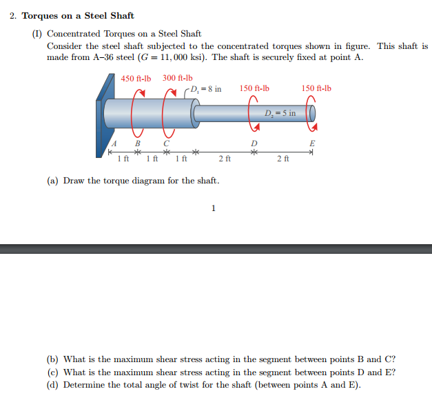
Solved Torques on a Steel Shaft Concentrated Torques on a ...
Draw the torque diagram for the shaft loaded as... Draw the torque diagram for the shaft loaded as shown in Fig. 8.41. Draw the torque diagram for the shaft loaded as shown in Fig. 8.41. Jan 10 2022 03:51 PM Expert's Answer Solution.pdf Next Previous

Transmission Shaft - an overview | ScienceDirect Topics
The propeller shaft is a component that transmits mechanical torque, rotation, and power. Driveshafts, driving shafts, tail shafts, and Cardan shafts are all names for these shafts. The driveshaft is used to transfer torque between components that are not directly connected due to distance or the need for relative motion.

A solid constant-diameter shaft is subjected to the torques ...
Shaft torsion - problems with sum (4) and torque diagram Options Previous Topic Next Topic Wanna join the discussion?! Login to your SMath Studio Forum forum account or Register a new forum account. Users browsing this topic SMath Studio Forum » SMath Studio » Questions » Shaft torsion - problems with sum (4) and torque diagram Forum Jump
Internal Loadings: The internal torque developed in segments ...
Samman LED Ditch Light Mount LED Pods Light Hood Hinge Mounting Bracket Compatible with Toyota Tacoma 2016-2020. $15.99. Pangburns Millionaire$ Candy, 9.75 Ounce Box, Pangburn's Millionaires Candy, Buttery Pecans, Creamy Caramel, Honey, and Mouthwatering Milk Chocolate; Texas Born, and Loved by All. $17.39.

Intro to FEA
Screw Conveyor Shafts | Component Guide
Theory | C3.3 Angle of Twist | Solid Mechanics I

Shaft Design Considerations - Vortarus Technologies LLC

A shaft is made of three circular segments AB,BC,CD and is ...
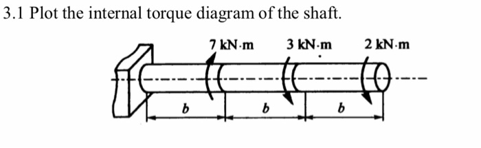
Solved 3.1 Plot the internal torque diagram of the shaft. 7 ...
Design of Square Key and Keyway (Wood Ruff) Stress, Shear and ...
Maximum shear stress and angle of twist, Mechanical Engineering

Problem 2 A solid shaft shown is formed of a brass with a ...
Mechanics of Materials Chapter 3 Torsion
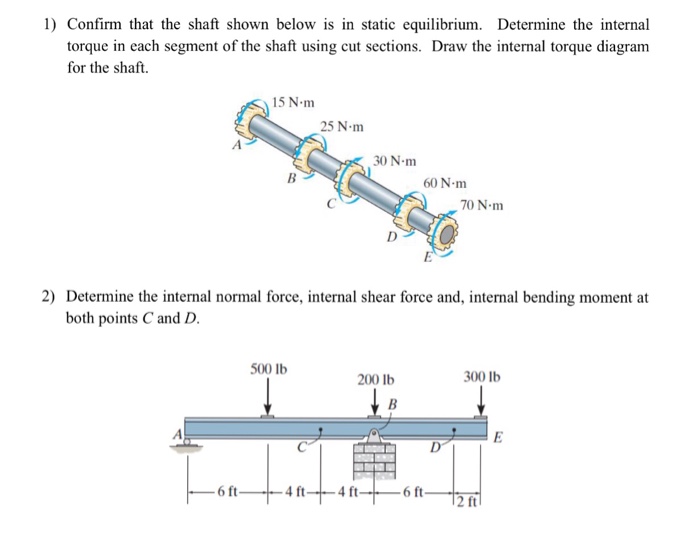
Solved Confirm that the shaft shown below is in static ...

Solved) - The 40mm diameter solid steel shaft is subjected to ...

Strain Gauge Based Torque Sensors & Measurement Experts ...
Mechanics of Materials Chapter 3 Torsion
0 Response to "44 torque diagram for shaft"
Post a Comment