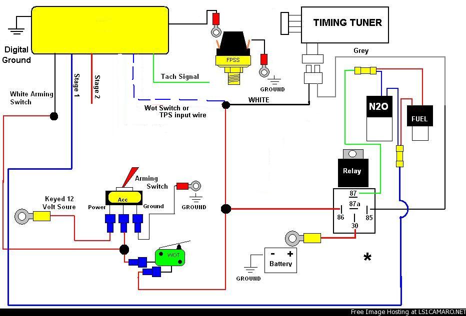
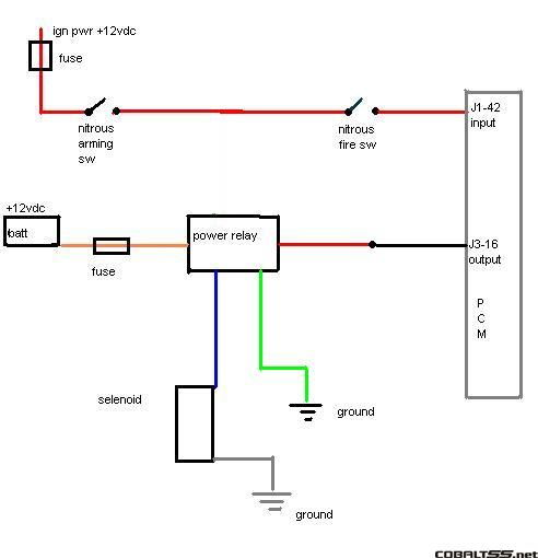
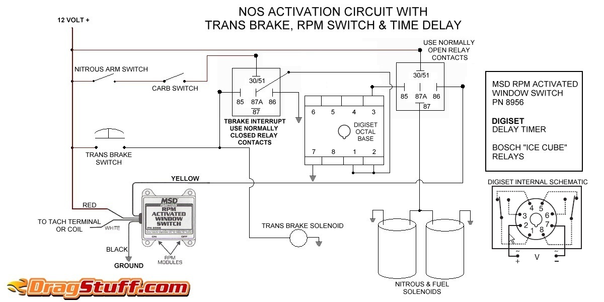
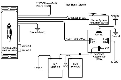
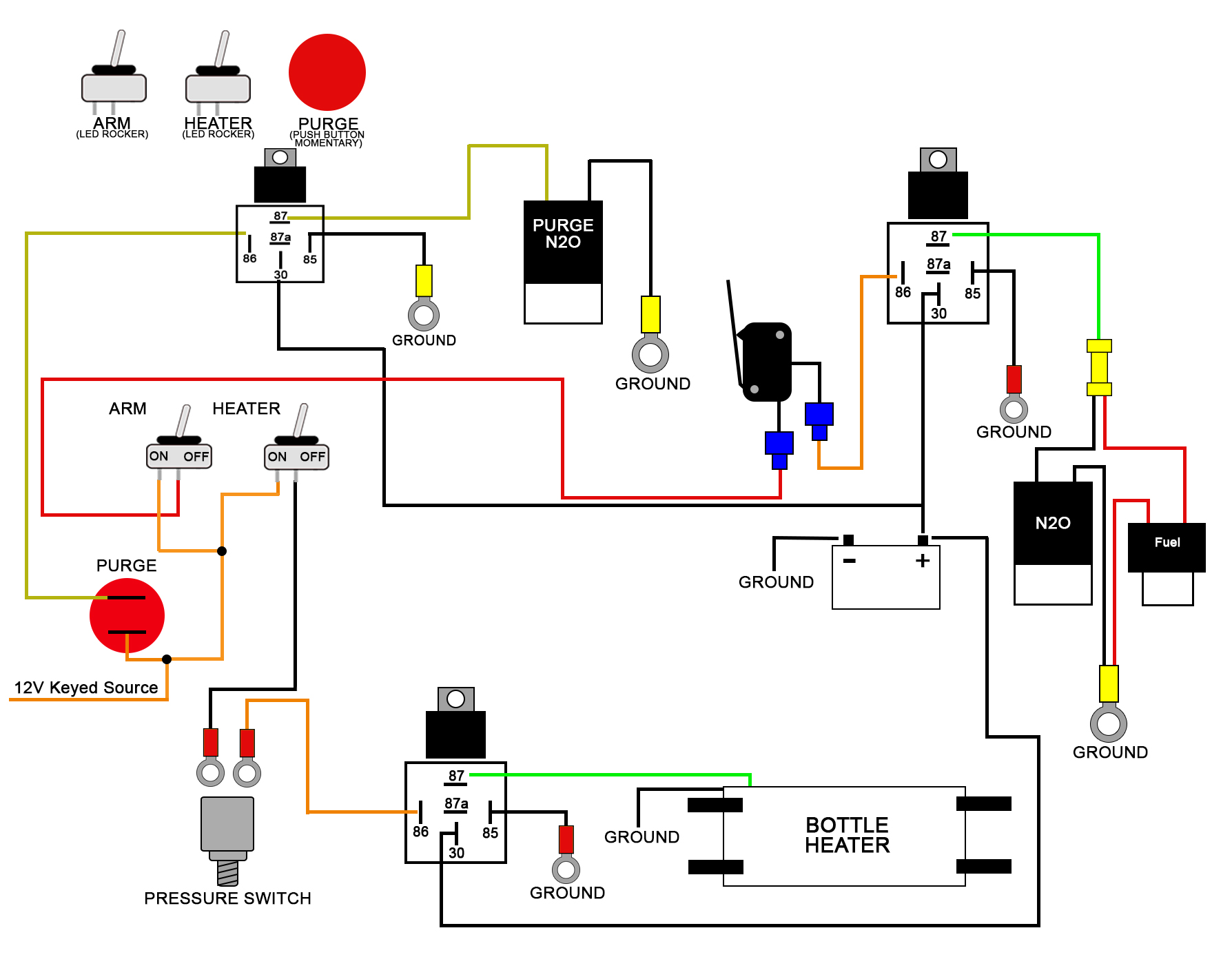
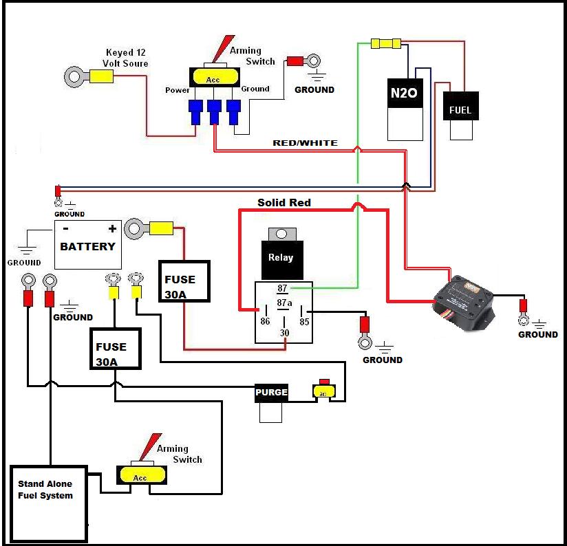
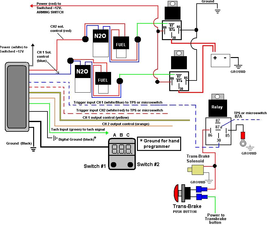
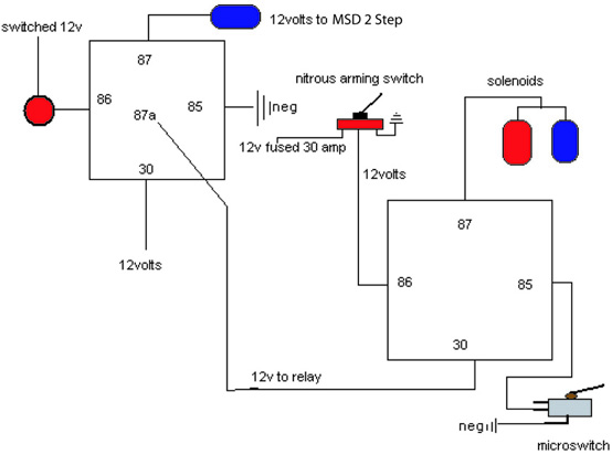
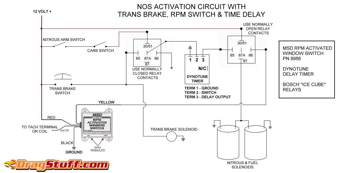
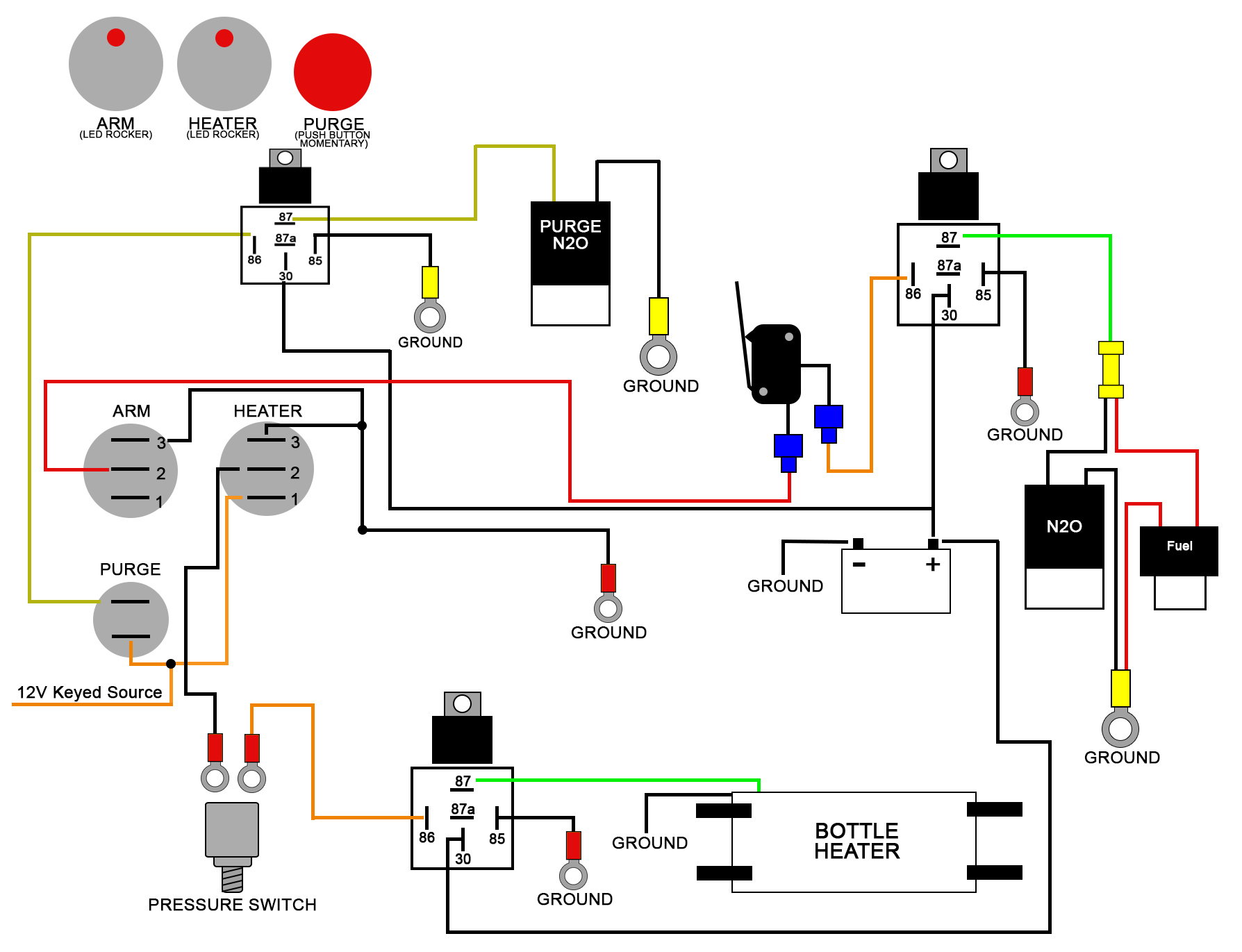
41 nitrous relay wiring diagram
How To Wire Horn Relay - U Wiring Wire harness ct90k1 ct90k2 ct90k3 1969 to 1972 121t 318e 6995. Use a multimeter to test the horn relay. Images Of Wiring Diagram For Horn Relay Harley Davidson A New Bosch Car Horn Motorcycle Wiring Electrical Circuit Diagram How to Wire a 6 Volt Horn. How to wire horn relay. Installation consisted of removing one […] 65 pontiac gto wiring diagram, gto v8 two wheel Fitech efi is dedicated to bringing the most advanced fuel injection systems on the planet supporting engines with up to 1200hp, 2x4, nitrous, boosted, and e85. Learn about starter solenoid maintenance in this free video on auto repair. Wiring diagram for reverb unit in 65 gto. Visit kijiji classifieds to buy, sell, or trade almost anything!
undicidieci.it › oil-pressure-gauge-wiring-diagramundicidieci.it IDENTIFICATION. Jun 03, 2011 · Wiring Diagram for gauges/panel. to the terminal marked “TACH” or on some systems, a single white wire with a spade terminal on it. Mar 10, 2014 · 1967 Mustang Interior Lights, Windshield Wiper and Gauges. Oil pressure sensor wiring diagram. Installation without relay. Fuel level sensor 41.
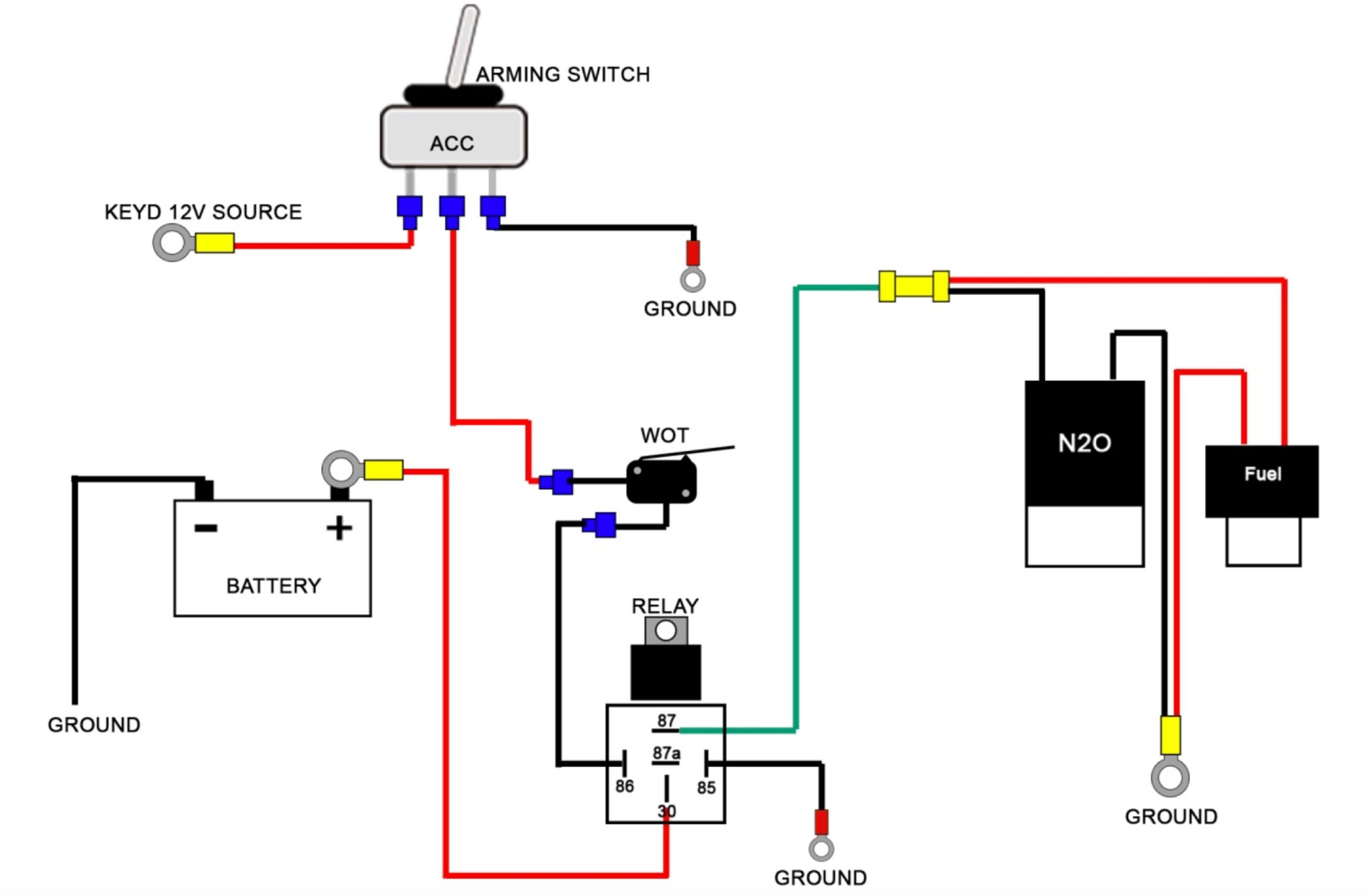
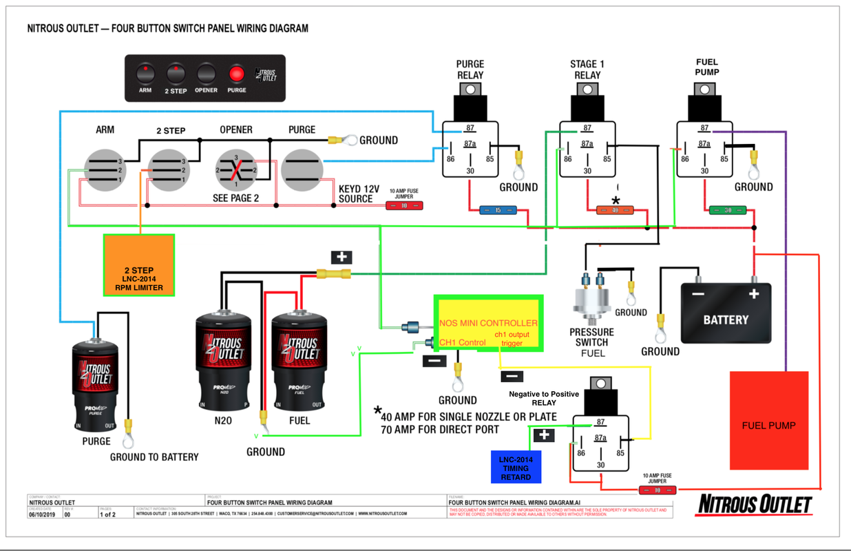
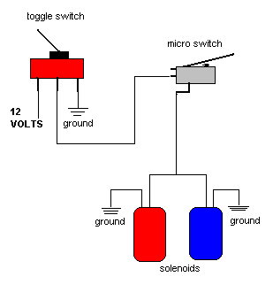
Nitrous relay wiring diagram
Digital Delay Wiring Diagram - Wiring View And Schematics ... Digital Delay. Digital Delay Switch Panels Elite Mega Panel. Digital Delay Nitorus Boards High Cur 2 Stage Nitrous Relay Board. 2399 Delay Diagram Agnd Versus Dgnd Etc Diy Build It And They Will Come Forum Kvr Audio. Timer Relay Dc 12v 10a Programmable Digital Time Cycle Delay Switch Module 1500w On Off Control 0 999 Second Min Hour Led Display ... Solenoid Trombetta Wiring [BD6O3Q] Trombetta Solenoid Wiring Diagram | Wirings Diagram Jul 15, 2020Trombetta Solenoid Wiring Trombetta 4 Wire Lawn Mower Starter Solenoid Wiring Diagram. Starter Solenoid Wiring Diagram - Without Starting Relay Type. In fact, its smart to just keep extras at your shop in case of needed repairs in the middle of the winter. Have a great day. Nitrous Wiring Schematic, Rc Trailer Wiring How do I got about wiring in and configuring the ECU to control the relay for the nitrous solenoid and fuel enrichment? Page 3, Wiring Diagrams Wiring Diagram #1 Factory Harness to Horn Horn To Nitrous Bottle Wiring Diagram #2 Factory Harness to Horn Horn To Nitrous Bottle 2007 Edelbrock Corporation Brochure #63-71940 +12V with Key On Black ...
Nitrous relay wiring diagram. 85 Corvette Ground Wiring Diagram - Build composter tip sliver Wiring Diagrams 85 Fbody ECM wiring diagrams 86 ECM pinout diagram 85 ECM wiring MAFMAS diagram copy1copy2 86 ECM wiring MAF diagram. 71 corvette horn relay wiring diagram from steering column 1968 1971 1984 chevy horns not working 1993 ac diagrams data 1994 gbodyforum 78 88 1981 1985 ignition switch schematic air full headlight 77 radio a942 ... wunderino-236.de › ford-toploader-diagram[email protected] - wunderino-236.de Y-BLOCK PERFORMANCE PARTS . Fiesta St Wiring Diagram. Au. Ford Toploader (small block) 6. As horsepower levels increased, Ford designed the Toploader and GM the Muncie. 2007/07/02 I need a diagram on the shifting forks on a 1991 t5 transmission in a ford mustang gt - Answered by a verified Ford Mechanic. . 13edgom4e. › products › fuel_systemsHolley EFI 558-102 LS1/6 (24x/1x) Engine Main Harness This harness is designed for LS1/6 Engines, from 1997-2004. This harness interfaces with 24x Crank and 1x Cam sensors. Read all Instructions before beginning!!!! - Nitrous Express (See wiring diagram). 8. Attach the white wire of the relay to ground. If using an optional fuel safety switch connect the switch between the white wire ...
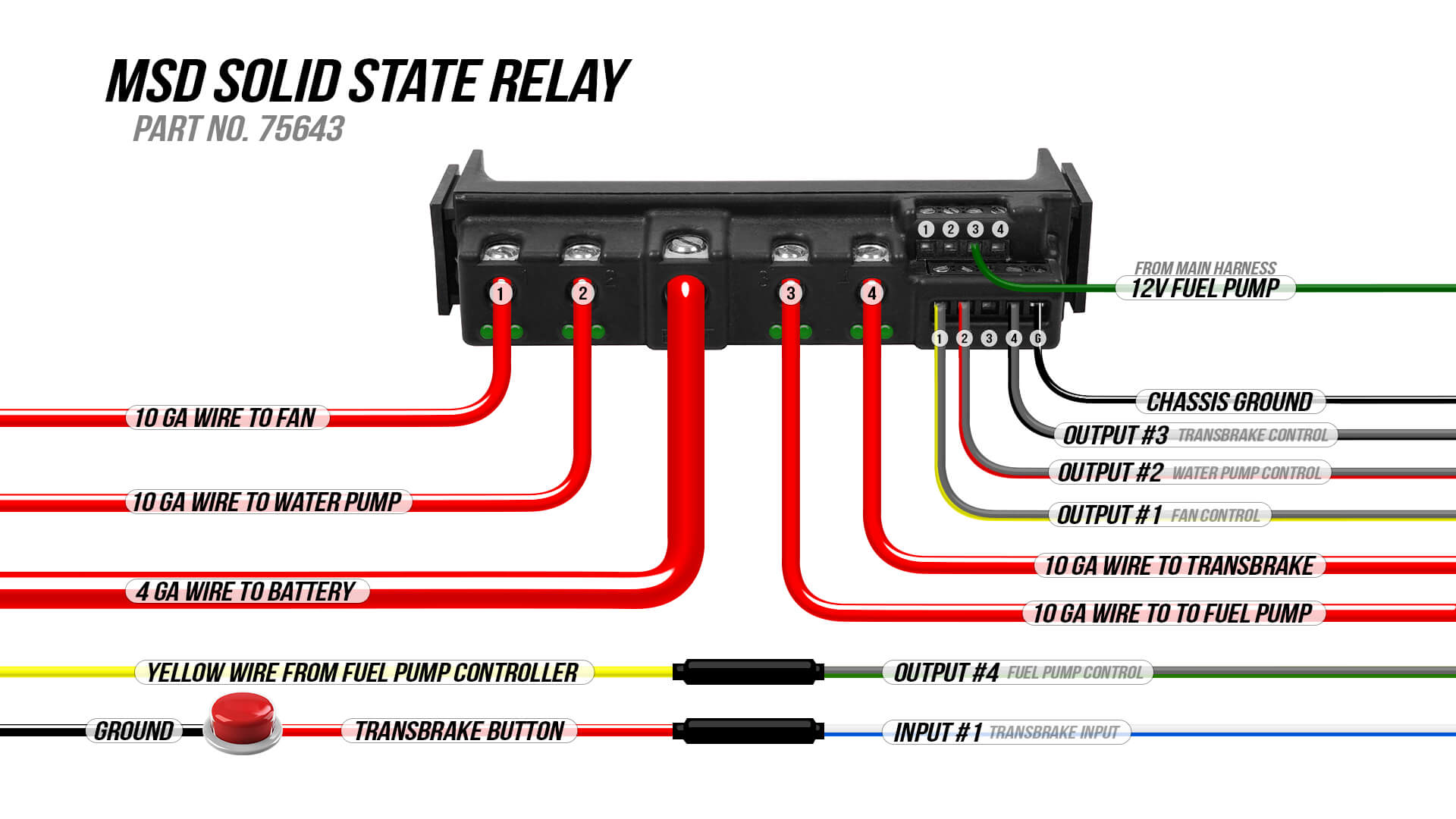
Nos Solid State Relay Wiring Diagram - Wiring View And ... Nos 15620nos Solid State Relay Ships Free At Efisystempro Com. Nos 15620nos Solid State Relay. Wiring Diagram Msd Solid State Relay 1985 Ford Mustang Holley My Garage. Msd Ignition S Solid State Relays Simplify Your Wiring Layout Holley Motor Life. How To Wire The Mgr Solid State Relay Huimultd. Nitrous System Wiring Diagrams Dragstuff. 5 Pin Flasher Relay Wiring Diagram - glassstationbc.com Aftermarket Wiring Harness KitVintage Auto Garage American Classic Car Truck Parts StoreDodge Dakota Wiring Diagrams/Pin Outs/Locations Lazada PH HelpcenterAmazon.com: 2-Pin Electric Flasher Relay, VOFONO 12V Heavy 12-Circuit Mini-Fuse Universal Hot Rod Wiring Harness KitHow to Determine the Fuse/Wire Size - Oznium BlogThrottle Position Sensor ... Nitrous Wiring Schematic, Rc Trailer Wiring Bosch Relay Wiring Diagram. The Holley is presently controlling all ignition timing functions, and can/will also control the nitrous, as far as it's activation, a preset time delay for activation, the RPM ON & OFF, and timing programmable. › 2015/01/02 › relay-caseRelay Case: How to Use Relays and Why You Need Them ... Jan 02, 2015 · High Wattage Headlights Wiring Diagram: This diagram is fo using high-wattage bulbs with stock headlights. Upgrading to 80-100 watt bulbs definitely requires the use of relays. The relay system bypasses the stock headlight wiring, which isn't heavy duty enough to handle the increased wattage of the new bulbs.
Tuned Port Injection Wiring Harness Diagram - Online ... Tuned port injection wiring harness diagram. 1 30273 plug port with socket hex oring, ‐6an 3. The standard gm tuned port injection systems we offer are 1990 92 speed density systems. Inlet/outlet port plugs (two installed on throttle body) (1) data com cable (1) 8 gigabyte sd card. Be sure to cap any unused vacuum ports. Fuel pump relay wiring question. - forums.holley.com This topic has been covered. I've come to understand that the thin blue wire from the ECU harness to the fuel pump relay is +12V negative/ground and the pink wire is +12V positive switched, same as the pink ignition on wire for everything else that needs to be on during run and start. Correct me if I'm wrong, please. My question is on the fuel pump relay #85 terminal, from the factory as +12V ... 42 msd 7al2 wiring diagram - leizbasi.blogspot.com Msd 7al2 To 8972 Wiring Diagram - schematron.org Msd 7al2 To 8972 Wiring Diagram 02.12.2018 02.12.2018 5 Comments on Msd 7al2 To 8972 Wiring Diagram Clipart and Vector, Best Selection of Msd Wiring Diagram clip art for your project Knowledge about msd 7al 2 wiring diagram has been submitted by Ella . msd 7al2 plus wiring diagram msd msd 7al 2 ignition control msd Wonderful Msd Wiring Diagram ... Efi Wiring Diagram Pdf - Wiring diagram online Wiring diagram index (ignition) this chart is designed to di rect the technician to the appropriate ignition harness wiring diagram. Source: Pantera 580 efi c pantera 1000 g panther 340 a panther 440 a panther 550 b powder special 500 efi c. 2008 polaris sportsman 500 wiring diagram pdf.
43 wiring diagram for holley sniper efi - diagram Holley Terminator X Stealth 4500 Efi System Black Finish. Part number 550-937F is a plug-and-play solution that includes a new harness to replace the crusty wiring in a Fox Mustang. Holley Terminator Wiring Diagram. Sniper EFI System Nitrous Wiring The diagram below is fairly self-explanatory but I will provide a few comments.
Get Motorcycle Horn Diagram Background - easywiring Snowmobile nitrous kits are the best way to make big power! 07/01/2022 · tickas horn wiring harness,universal 12v/24v horn cable relay for grille mount blast tone horns motorcycle horn wire wiring harness kit for car truck relay. 1955 chevy pu wiring pickup diagram 55 harness diagrams lovely 85 and 86 are connected to the existing horn control ...
Fox Body Engine Bay Diagram (1986-1993) - LMR.com Fox Body Engine Bay Diagram (1986-1993) Created by Taylor Ward. Last Updated 9/7/2021. LMR breaks down each part in your Fox Body's engine bay with this easy to use infographic. Find out which parts you may be missing and pick up the direct replacement parts you need. Show More Show Less. Viewing this install and using the information shared is ...
sebastian-goers.de › e46-ignition-switch-testsebastian-goers.de In many cars, there is a special procedure to remove and install the brake light switch. 3ef Bmw E46 Cd Changer Wiring Diagram Epanel Digital Books. 61361729004) To test remove this relay and switch on the ignition then gently Turning on the ignition will complete the syncing process for each of the fobs you've connected.
Bucket Truck Wiring Diagrams Bucket Truck Wiring Diagrams. The instructions are easy to understand and include diagrams of proper vehicle positioning. Spend some time in the left hand lane. Zips AW Direct in association with Beacon Software offers you a convenient way to find the right way to tow vehicles of nearly every make and model. With our new 338 to 1 ratio ring and ...
Holley Term X into Fox... any watch-out-fors? | Ford ... 326 Posts. #4 · Jun 23, 2021. You need to split your harness and ferret out your gauge sending unit wires, A/C circuit wires and your air bag sensors and relay wiring. Get a good wiring diagram and take it all the way back to the brown connector near the driver side firewall. I bought a bunch of Holley wire loom so it all looks like it belongs ...
Bosch Style Relay Boxes — Choose 4, 6 or 8 Relays | MGI ... Nitrous Trans-Brake Circuit. A nitrous trans-brake system is a great example of SPDT wiring that uses both the N.C. and N.O. relay box circuits. See the RCPX Nitrous Trans-Brake Wiring Diagram. In this case, the N.C. nitrous circuit (with its own arming switch) is active only when the trans-brake switch is open.
Relay switch - Harley Davidson Forums Discussion Starter · #2 · May 3, 2021. I'm working on a 2005 Sportster custom. I've got a starter relay next to the fuse box this thing is under the ignition control and above the battery looks like it's just sliced in there cuz the other two connection connects. Is it by chance a fuel pump relay or a different relate switch.
WIRING DIAGRAM FOR SINGLE STAGE N2 O WITH ... Solenoid. Battery Ground. WIRING DIAGRAM FOR SINGLE STAGE N2. O WITH TRANSBRAKE. WITH OPTIONAL FUEL SAFETY SWITCH. NOTES: 1) Bottom view of all relays.1 page
Online Wiring Diagram A wiring diagram usually gives suggestion approximately the relative point of view and treaty of. Here is a picture gallery about bosch 4 pin relay wiring diagram complete with the description of the image please find the image you need. Bosch 4 Prong Relay Wiring Diagram Manual E-Books Bosch 4 Pin Relay Wiring Diagram.
Automotive Wiring And Electrical Systems Vol 2 Projects Wiring. Filter by Availability Nitrous Oxide Systems (NOS) 15620NOS - NOS Solid State Relays. Relays, Solid State, 40 amps, 5-20 V, Single Pole, Female Connector Terminal Type, 24 in. Pigtail, Nitrous Usage, Each SPAL Automotive USA FRH - Spal Electric Fan Relay Wiring Kits.If you like
How To Wire A 4 Pin Relay Fuel Pump - U Wiring About Fuel Relay Ml350 2015 Location Mercedes Pump original fuel pump relay location position l which is then connected to the fuel pump relay that has been relocated to the top of the panel if your car has factory installed heated seats the relays for this option are under each front seat 443919533a thread vw golf agu engine wiring diagram a.
Most Viewed Nos Relay Wiring Diagram Inspirations The power contacts in the relay will carry a maximum of 30 amps. Nitrous and transbrake wiring diagram. Learn how to install your nitrous kit, bottle heater, purge kit etc. Nitrous wiring diagram with transbrake. Use only the diagram shown in this instruction booklet. Search the web for a typical nitrous wiring diagram, should be easy to find.
› pages › manualsEnglish Manuals - FuelTech USA FT450/550 4 Cylinder Universal Wiring Harness Manual ... Staging / Brake Control Relay Diagram ... Size: 56 KB: Nitrous Solid State Relay Diagram Version: 1.0 | Size ...
Water Pump Pressure Switch Wiring Diagram - Wirings Diagram Water Pump Pressure Switch Wiring Diagram - square d water pump pressure switch wiring diagram, water pump pressure control switch wiring diagram, water pump pressure switch wiring diagram, Every electrical structure is composed of various different components. Each part should be placed and connected with other parts in particular way. Otherwise, the structure won't work as it should be.
Nos Wiring Diagram Transbrake - BSIQAE Nitrous Wiring Diagrams. The stud labeled 2. A Remarkable Last Minute Holiday Tour Christmas Projects Christmas Celebrations Holiday Tours . Nitrous system wiring diagrams dragstuff with transbrake diagram nos and ls1tech leash single stage relay board double throw 60 amp pn 15515 help 6sd 2step wot controller 2 step holley performance products forums trans brake express manualzz new 408 build ...
Mustang Complete Wiring Harnesses | Wiring Harness Kits 1979-93 Mustang Complete Wiring Harnesses. American Autowire Classic Update Wiring Harness (87-93) #AAW-510547. In Stock. $962.10. Pro-M EFI Engine Management System (79-85) #PMA-EFI7985. Dropships from Supplier!
› docs › MicroSquirtHDWManualRSMicrosquirt Hardware Manual - EFI Source Section 3.3 is the external wiring diagram, you should print that out. Section 6 covers the many different tach trigger input schemes (wheel decoders) that exist to support numerous OEM trigger wheel patterns.
3 Plug Ecu Wiring Diagram For Saxo 1 1 Read Online 3 Plug Ecu Wiring Diagram For Saxo 1 1 c frc_j3:c5 aq:1 b mcsc:a9 f61a1-0.8 hb:2 d a131b.a:4 f15a1-5.0 bi:3 … BMW - electrical systems - WIRIN… Basic Safe Electric Fuel Pump Wiring Diagram This is the basic wiring diagram for SAFE electric fuel pump wiring. The diagram is color coded per circuit and only a few things may need to ...
Relay & Wiring Thoughts - forums.holley.com Hello. I'm using a universal HP EFI harness and have added in two 554-112 coil driver modules (and Ford Coyote coils if it's at all relevant). Those each require switched +12V. The relay within the HP harness powers the fuel pump positive output wire and the injectors. Since I have a separate fuel pump relay, powering a relay with a relay seems redundant so my idea was this: -Red wire to HP ...
Nitrous Wiring Schematic, Rc Trailer Wiring How do I got about wiring in and configuring the ECU to control the relay for the nitrous solenoid and fuel enrichment? Page 3, Wiring Diagrams Wiring Diagram #1 Factory Harness to Horn Horn To Nitrous Bottle Wiring Diagram #2 Factory Harness to Horn Horn To Nitrous Bottle 2007 Edelbrock Corporation Brochure #63-71940 +12V with Key On Black ...
Solenoid Trombetta Wiring [BD6O3Q] Trombetta Solenoid Wiring Diagram | Wirings Diagram Jul 15, 2020Trombetta Solenoid Wiring Trombetta 4 Wire Lawn Mower Starter Solenoid Wiring Diagram. Starter Solenoid Wiring Diagram - Without Starting Relay Type. In fact, its smart to just keep extras at your shop in case of needed repairs in the middle of the winter. Have a great day.
Digital Delay Wiring Diagram - Wiring View And Schematics ... Digital Delay. Digital Delay Switch Panels Elite Mega Panel. Digital Delay Nitorus Boards High Cur 2 Stage Nitrous Relay Board. 2399 Delay Diagram Agnd Versus Dgnd Etc Diy Build It And They Will Come Forum Kvr Audio. Timer Relay Dc 12v 10a Programmable Digital Time Cycle Delay Switch Module 1500w On Off Control 0 999 Second Min Hour Led Display ...














0 Response to "41 nitrous relay wiring diagram"
Post a Comment