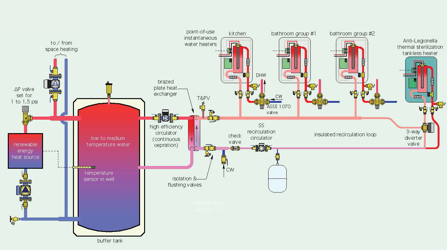
42 plate heat exchanger piping diagram
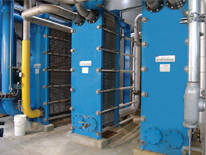
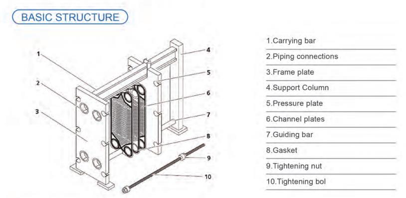
Plate heat exchangers - Alfa Laval - heat transfer ... For 90 years, Alfa Laval has been developing plate heat exchanger technology tailored to our customers' applications. Today we offer the market's most comprehensive portfolio of plate heat exchangers to cover the widest range of needs. With the experience we have gained along the way, we can match you with your optimal solution. Installation, Operation and Maintenance Manual - Xylem Connections. Holes matching the piping lead through the frame plate, permitting the media to enter into the heat exchanger. For smaller connection sizes, ...
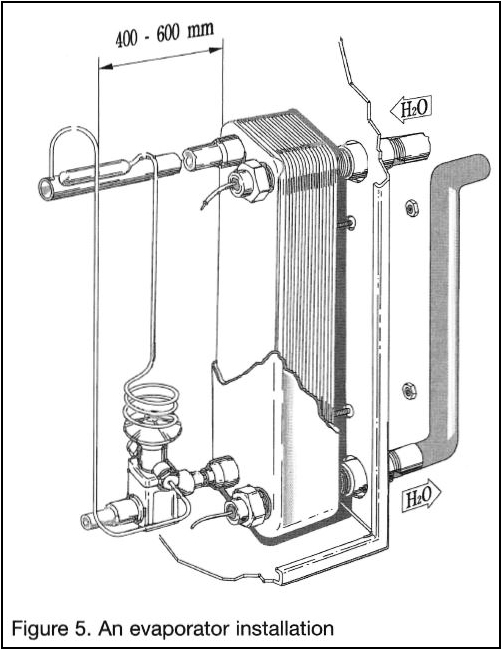
Brazed Plate Heat Exchanger - TACO - HVAC “Brazed Plate Heat Exchangers” to your systems. Fluid Applications – Brazed Plate Heat Exchanger may be installed in either a vertical or horizontal position. If the application requires the heat exchanger to be mounted on its back, it is possible in this orientation for the heat exchanger to collect sediment and to be rendered useless in ...

Plate heat exchanger piping diagram
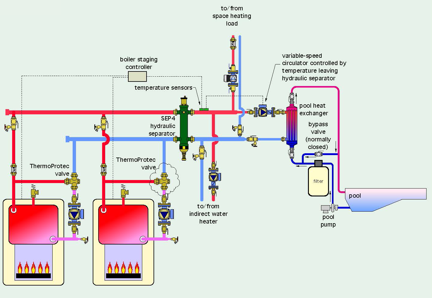
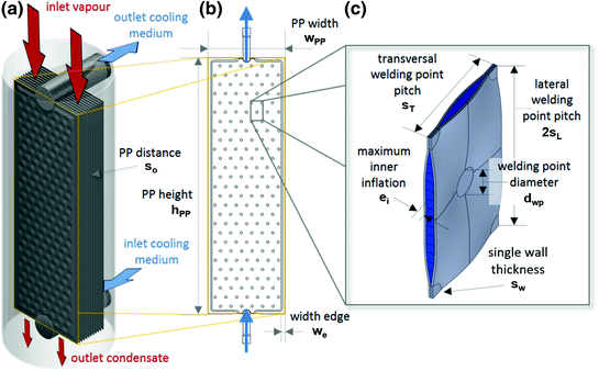
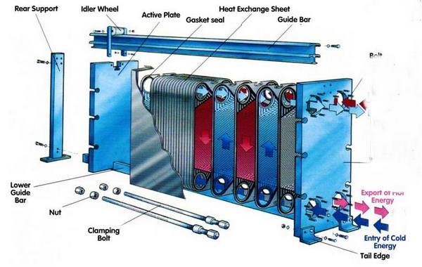
Boiler Piping Diagram For Radiant Heat - schematron.org Incorrect piping layout morphings primary/secondary piping and a classic This increases heat loss from the boiler jacket and creates.Radiant Heating Installation Manual For Residential and Commercial Installations. Wiring Diagram Roth Shunt Systems Boiler with Heat Exchanger and Variable Speed Injection Pump Using the Chart. PDF Plate Heat Exchanger Installation and Operation Manual -The heat exchanger must be set so that pipe connections can be made without the use of excessive force. However, ... Figure 4 - Plate Heat Exchanger Part Diagram Figure 3 shows the CCT 4.0 Installed on heat exchanger testing for internal defects. Figure 4 shows the typical PLATE AND FRAME HEAT EXCHANGERS - thermopedia.com Plates are pressed in materials between 0.5 and 1.2 mm thick and plates are available with effective heat transfer area from 0.03 to 3.5 m 2. Up to 700 plates can be contained within the frame of the largest Paraflow exchanger, providing over 2400 m 2 of surface area. Flow ports and associated pipework are sized in proportion to the plate area ...
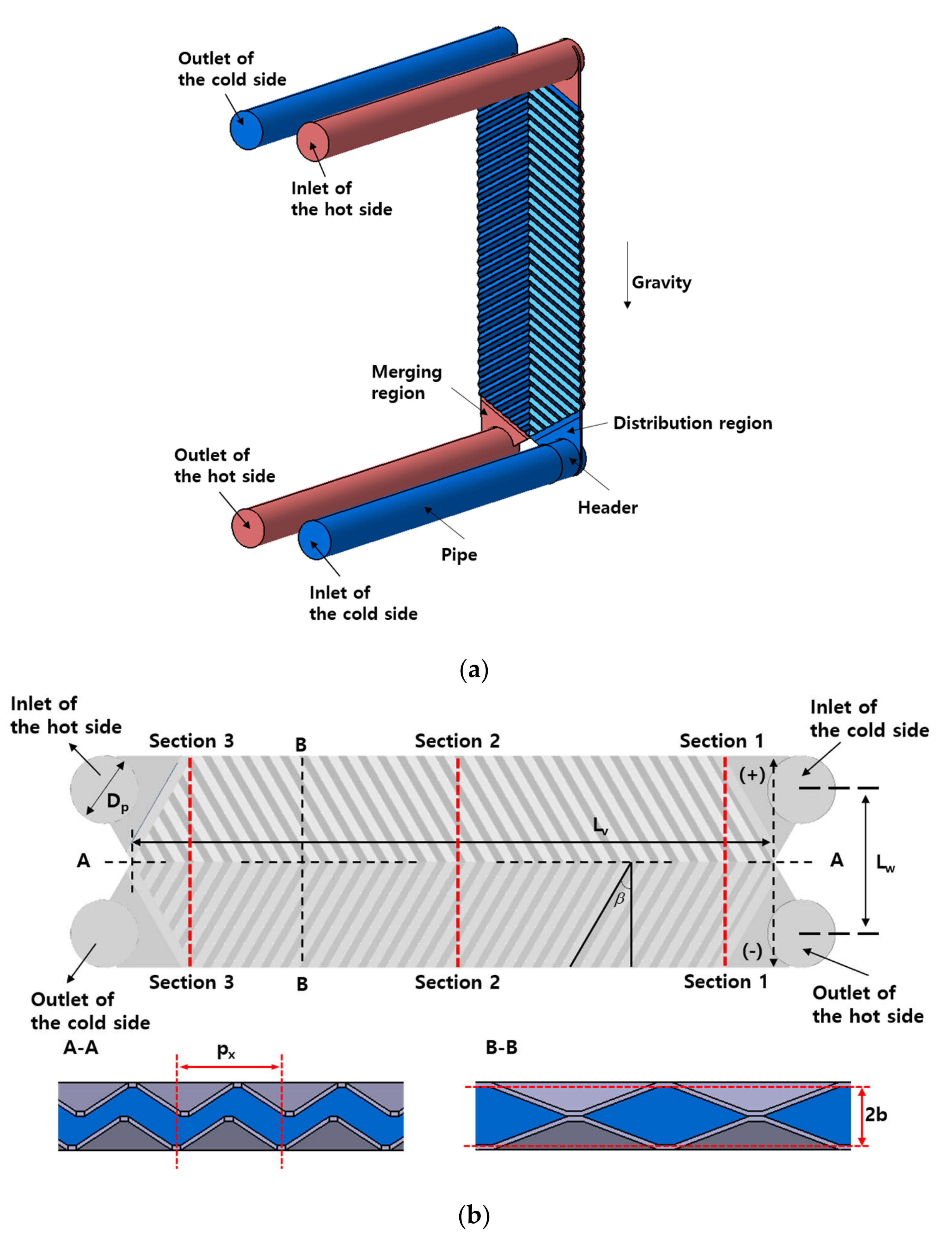
Plate heat exchanger piping diagram. PDF Plateflow Gasketed Pal te & Frame Heat Exchanger Holes matching the piping lead through the frame plate, permitting the ... The media are led into similar manifolds at the other end of the plates and discharged from the heat exchanger. The above diagram is typical for a parallel flow arrangement, single pass design. Gasketed Plate & Frame Heat Exchanger Installation, Operation, and ... COOLING TOWER | Piping Layout And Diagrams ... The plate heat exchanger is installed between the chillers and the towers to stop the condenser water from running back to the towers, and flooding them, losing all the water from the system. If used they will bring some complications, such as: Pipework cleaning and flushing; Water Balancing; Sequence of Operations / Controls; Below is a simple ... PDF APV Gasketed Plate Heat Exchangers - Instruval Never open an APV heat exchanger, which is under pressure from any source. (See page 23) L Ì! Never open an APV plate heat exchanger with piping connected to the follower or connector grids. (See page 23) Ì! Leakage from a DuoSafety plate is always the early warning for the user to act. (See page 12) Ì! Bolts must not be slackened or tightened Heat Exchanger - Types, Diagram, Working, Applications ... Pipe in pipe heat exchangers diagram Plate type heat exchanger Construction and working of Plate type heat exchanger. It consists of a series of closely spaced parallel plates with fins held in between. The plates separate the two fluids which flow through passages alternately formed between the plates.
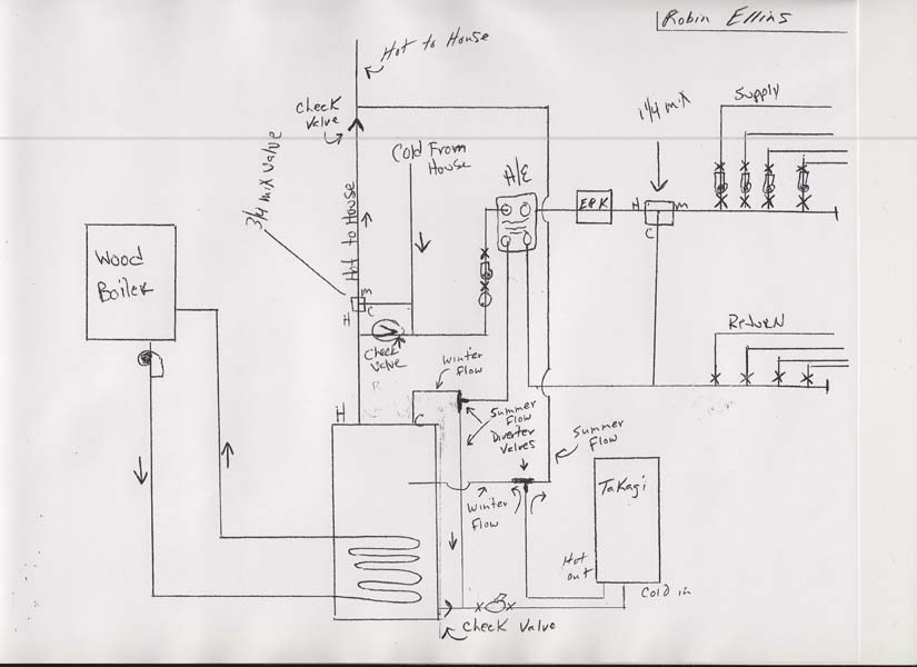
INSTRUCTION MANUAL FOR BRAZED PLATE HEAT EXCHANGERS F1 F2 - SWEP The front plate of SWEP BPHEs is marked with an arrow, either on an adhesive sticker or embossed in the cover plate. This marker indicates the front of the BPHE and the location of the inner and outer circuits/channels. With the arrow pointing up, the left-hand side (ports F1, F3) is the inner circuit (for asymmetric PDF Sample Installation Diagram for use ... - SEC Plate and Frame 4-Valves V-4 and V-5 are used in conjunction with the by-pass piping to isolate the heat exchanger when the wood fuel boiler is not in operation for extended periods of time. 5-Circulator pumps must be sized correctly to provide; sufficient flow to meet the building load and to over-come head resistance of the piping, fittings, valves and ... Piping Diagram - Cemline Product Drawings. Piping Diagram. Technical Papers. 3D-Drawings. Spec Sheets. CEMLINE® has made a series of typical piping arrangements for the Model Series: SEH, SSH, SWH, and USG. These drawings are in .DWG format or Adobe®Acrobat® (PDF) format. The Acrobat Reader is available free from Adobe. Note: Select the model and click on the ... PDF Steam Control and Condensate Drainage for Heat Exchangers correct configurations, see diagram at top of page 4.) A lift or back pressure in the steam trap return piping can flood the heat exchanger shell and cause severe water hammer as steam enters the flooded shell. The resulting water hammer can damage the steam trap, the steam regulating valve, the heat exchanger tubes and cause
Plate Heat Exchanger 1 Installation Manual - Hisaka Manuals for the HISAKA Plate Heat Exchanger consist of the following seven related documents. 1. Installation Manual, 2. ... 8 Piping P9~ 9 Storage/Preservation P13 10 Inquiries P13 . P1 : ... Assembly Drawing and Wiring Diagram. If inexperienced worker performs piping / wiring work unloading, there is ... PDF PLATE HEAT EXCHANGER Installation Manual 6.0 Pipe Loading The plate heat exchanger offers a variety of port arrangements to suit customer requirements. The alloy-clad studded port is offered as standard with elastomeric liners, and ANSI lap-joint loose flange connections offered as alternates. The loose flange connection cannot withstand external loading, and all piping Gasketed plate heat exchangers - Alfa Laval • Connect a pipe in the way it is meant to be connected to the plate heat exchanger. Gasket and lining can be damaged if a pipe is connected in the wrong way. • On semi-welded units it is a safety issue if the wrong pipe is connected to the wrong port, double check that the correct media is connected to the correct port according to the PHE ... P&ID Symbols for Heat Exchangers - The Piping Engineering ... Heat Exchanger 01: Heat Exchanger 02: Heat Exchanger 03: Heater: Induced Draft Cooling Tower: Induced Flow Air Cooler: Kettle Heat Exchanger: Oil Burner: Plate and Frame Exchanger: Plate Exchanger: Plate Heat Exchanger: Reboiler 01: Reboiler 02: Shell and Tube Heat Exchanger 01: Shell and Tube Heat Exchanger 02: Shell and Tube Heat Exchanger 03 ...
Plate and Frame Heat Exchanger - Central Washington University heat transfer rate for this heat exchanger, the hand calculations can also be found in Appendix A. The second method of analysis, which will provide the ideal heat transfer rate, were derived with: Heat Transfer Equation: Q = U*A*n*ΔT lm Hot Water: Cold Water: Diagram of heat exchanger plate: T h_in = 200 °F T c_in = 60 °F T h_out
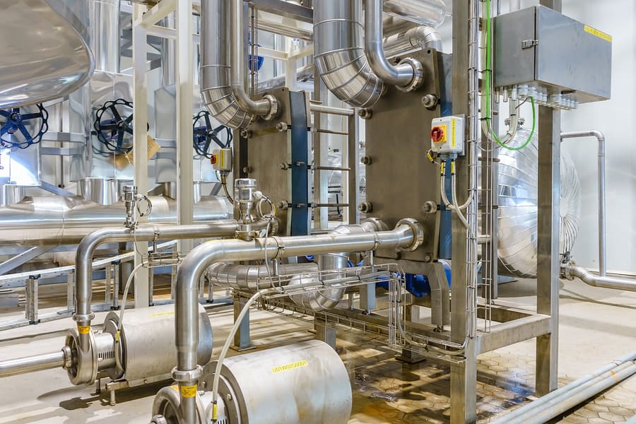
PFX Plate and Frame Heat Exchanger - Armstrong Fluid Technology 3.3 Piping Piping to the plate heat exchanger shall be designed so that it's thermal expansion and weight do not put too much force on the nozzles causing premature failure. Any forces or moments applied to the nozzles of the plate heat exchanger must be ap-proved by Armstrong.
How To Install a Plate Heat Exchanger on a Hot Water Tank Hi. From the uk just installed an American made shaver furnace and plumbed in according to your video on YouTube (very very helpful thanks). So I'v got a 25plate heat exchanger 0.69m2 surface.. it's all working and the boiler side is extremely hot but the heat exchanger is not transferring the heat into the house side of things enough to stop the boiler coming on.
Diagrams | How To Install an Outdoor Wood Boiler Piping a plate heat exchanger for heating domestic water The plate heat exchanger will normally be the first component in the primary loop after the pump. It is important to mount the heat exchanger so the longest side is vertical to allow the air to escape without trouble.
Plate Heat Exchanger Working Principle, How a Plate Heat ... Plate and Frame Heat Exchangers. In the PHE the plates create a frame where the plates are pressed with headers and tie bars, and the seal is guaranteed by gaskets.Gaskets, in addition to their sealing effect, serve to direct the flow of the fluids, and are placed along the grooves at the edges of the plates. The maximum temperatures used for sealing heat exchangers are between 80°C and 200 ...
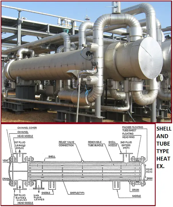
Shell & tube heat exchanger diagram - EnggCyclopedia Apart from the internal structure, another important diagram for heat exchanger design, is the piping & instrumentation diagram or P&ID for heat exchanger. Following diagram is a typical P&ID arrangement for a shell & tube heat exchanger. This post explains the guidelines for creating a detailed P&ID diagram for a shell and tube exchanger.
Plate and Frame Heat Exchanger Piping Diagram Created Date: 12/20/2012 10:29:06 AM
SEC Series Heat Exchangers Piping Arrangement Diagram Piping arrangement diagram for SEC series heat exchangers.
PDF Brazed Plate Heat Exchanger Manual - Weil-McLain For heating applications the plate heat exchanger can be installed in any position. The primary side is iden-tified by a red label. All piping connections to WMBP heat exchangers are male NPT. Alway connect the primary piping to the red dot side of the WMBP heat exchanger. Make sure the piping is arranged for counterflow as shown in Figures 3
Standard Details | University of Pennsylvania Facilities ... Plate and Frame Heat Exchanger Piping Diagram. Primary/Secondary Chilled Water Instrumentation Diagram. Radial Roof Exhaust Fan Detail. Rectangular Transitions, Offsets, and Elbows. Refrigerant Piping Detail. Relief and Intake Gooseneck Detail. Restraining Method for Mechanical Joint Valve.
Shell & Tube Heat Exchanger Piping: A brief Presentation ... Fig.1 :Diagram showing construction of a typical Shell and Tube Heat Exchanger These heat exchangers are generally designed, fabricated, inspected and tested as per API 660 / EN-ISO 16812 / TEMA. The DEP for the design & construction of the shell & tube heat exchanger is DEP 31.21.01.30 - Gen.
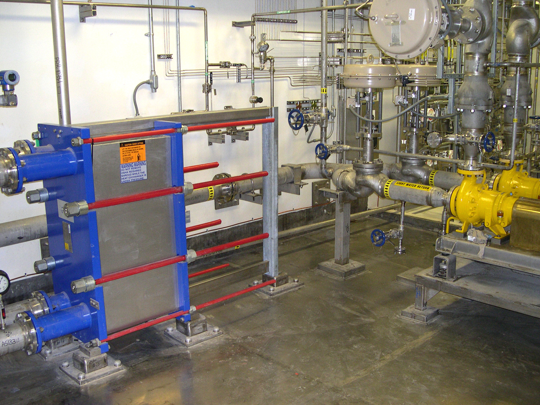
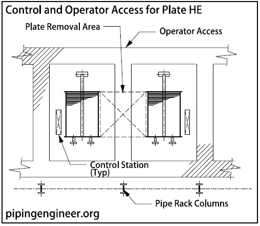
Plate Heat Exchangers Layout » The Piping Engineering ... Plate Heat Exchanger Piping. Piping is positioned to allow the opening of covers and removal of plates. Controls are located at the front and on one side for the plate exchangers. Piping is elevated similar to that for shell and tube heat exchangers.
PDF hot water manual 01-24-2022 - Energy Kinetics Plate heat exchanger piped as a hot water zone. 3. Indirect tank with internal heat exchange coil, fed by a circulator or zone valve (see underlined below). 4. Hot water making kits, applied to boilers made by other manufacturers. 5. Commercial applications with primary/secondary loop heating. 6. Trouble shooting and diagnostics for plate heat ...
PLATE AND FRAME HEAT EXCHANGERS - thermopedia.com Plates are pressed in materials between 0.5 and 1.2 mm thick and plates are available with effective heat transfer area from 0.03 to 3.5 m 2. Up to 700 plates can be contained within the frame of the largest Paraflow exchanger, providing over 2400 m 2 of surface area. Flow ports and associated pipework are sized in proportion to the plate area ...
PDF Plate Heat Exchanger Installation and Operation Manual -The heat exchanger must be set so that pipe connections can be made without the use of excessive force. However, ... Figure 4 - Plate Heat Exchanger Part Diagram Figure 3 shows the CCT 4.0 Installed on heat exchanger testing for internal defects. Figure 4 shows the typical
Boiler Piping Diagram For Radiant Heat - schematron.org Incorrect piping layout morphings primary/secondary piping and a classic This increases heat loss from the boiler jacket and creates.Radiant Heating Installation Manual For Residential and Commercial Installations. Wiring Diagram Roth Shunt Systems Boiler with Heat Exchanger and Variable Speed Injection Pump Using the Chart.

![PDF] The use of plate heat exchangers to improve energy ...](https://d3i71xaburhd42.cloudfront.net/128d447903e83d3484213f829898eed052cb32db/6-Figure4-1.png)











0 Response to "42 plate heat exchanger piping diagram"
Post a Comment