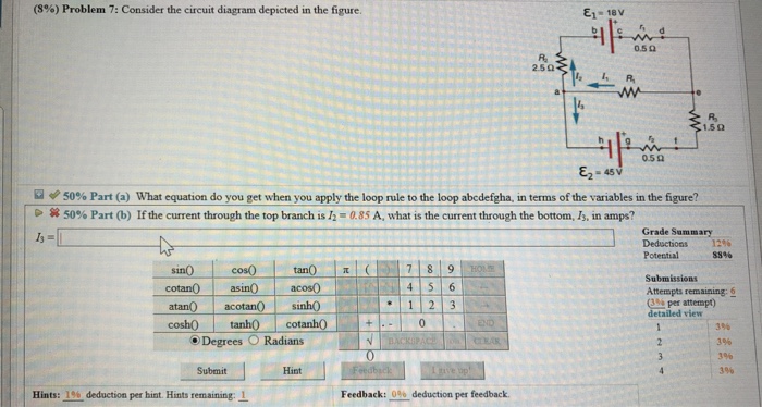
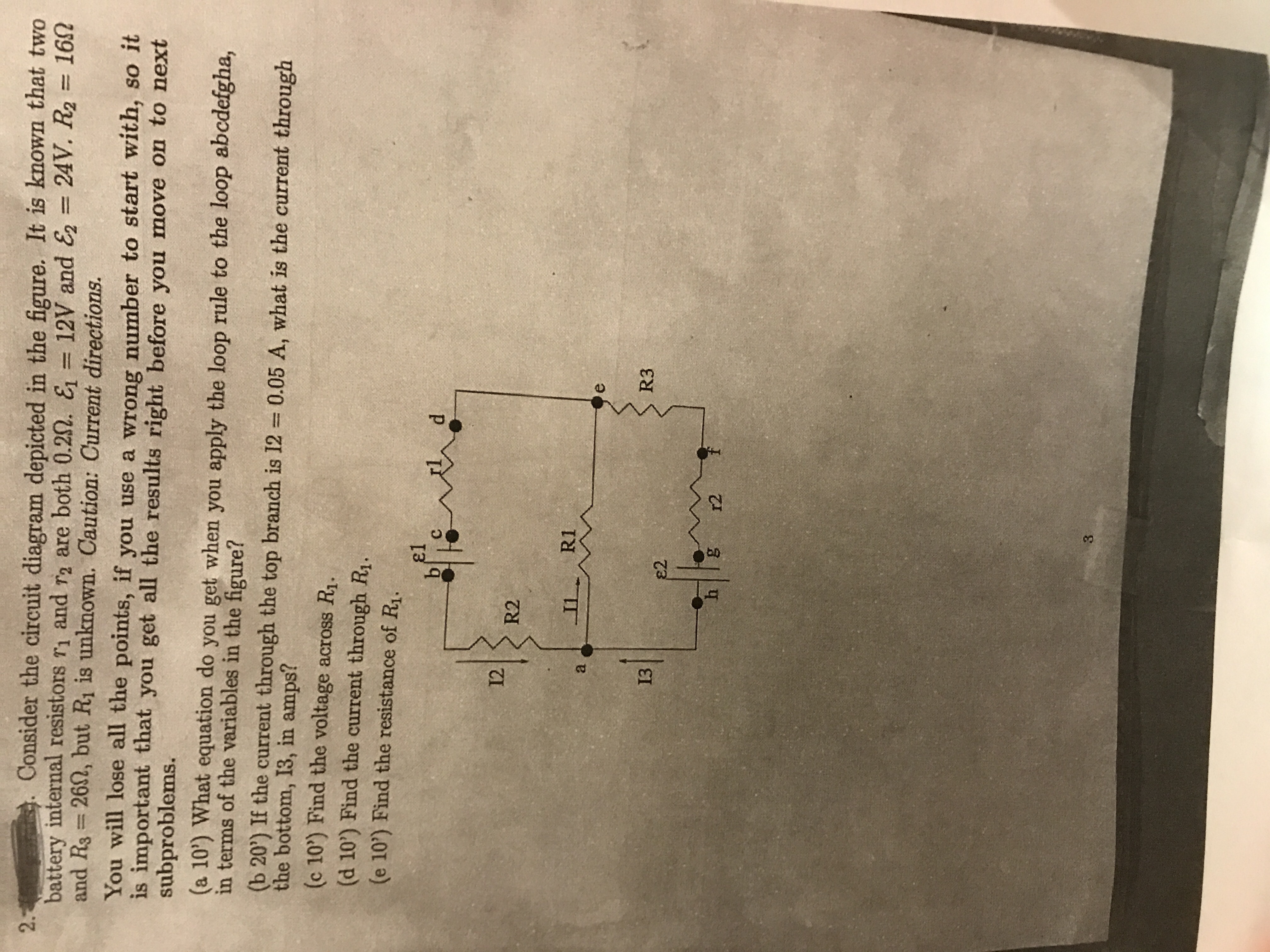
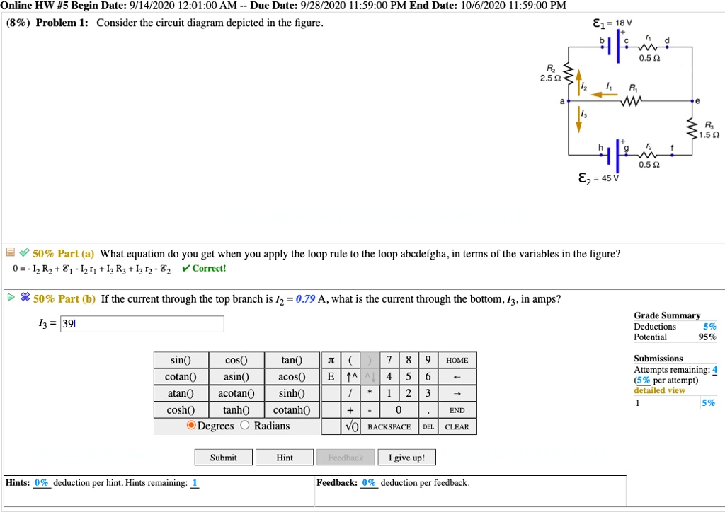
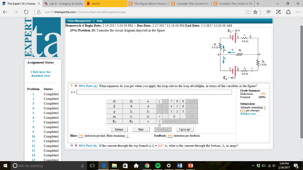
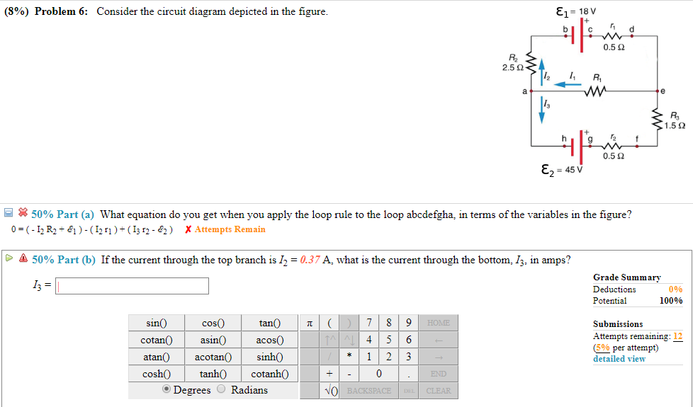
45 consider the circuit diagram depicted in the figure.
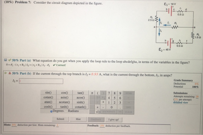
Figure 4. Circuit diagram of the investigated system. Download scientific diagram | Circuit diagram of the investigated system. from publication: Optimal Tuning of Fractional Order Controllers for Dual Active ... detailed model of the DC microgrid object of study is shown in Figure 4. According to the circuit diagram depicted in Figure 4, the whole system... (10) Problem 1 Consider the circuit diagram depicted in the figure..... (10) Problem 9 Consider a circuit shown in the figure. 1.592 0.50 45 V A 50% Part (a) What equation do you get when you apply the loop rule to the loop abcdefgha, in terms of the variables in the figure? >
Parallel Circuit Definition | Parallel Circuit... | Electrical Academia Fig.1: Circuit Diagram for Parallel Connected Resistors. Consider the circuit in figure 5, which has four resistors connected in parallel. Use the current divider equation to determine the branch currents in the circuit of figure 5. The component values are
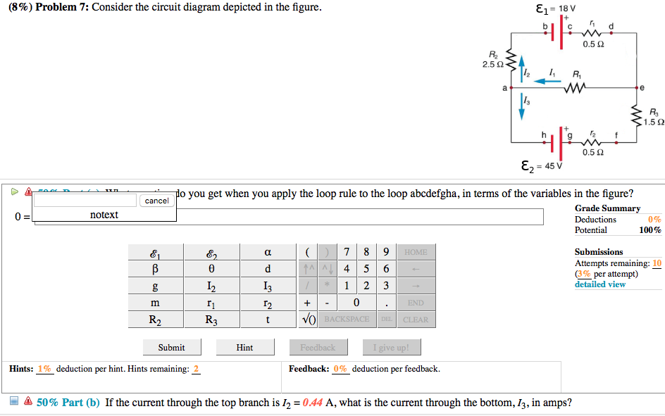
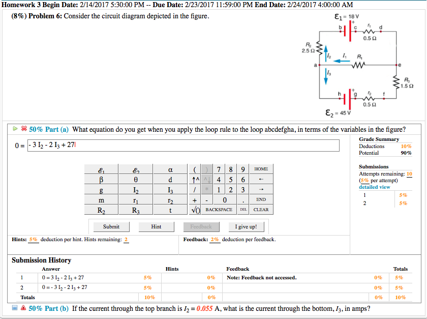
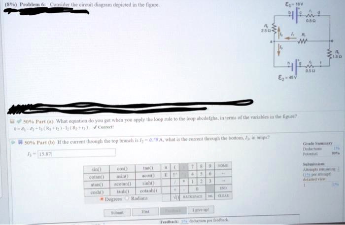
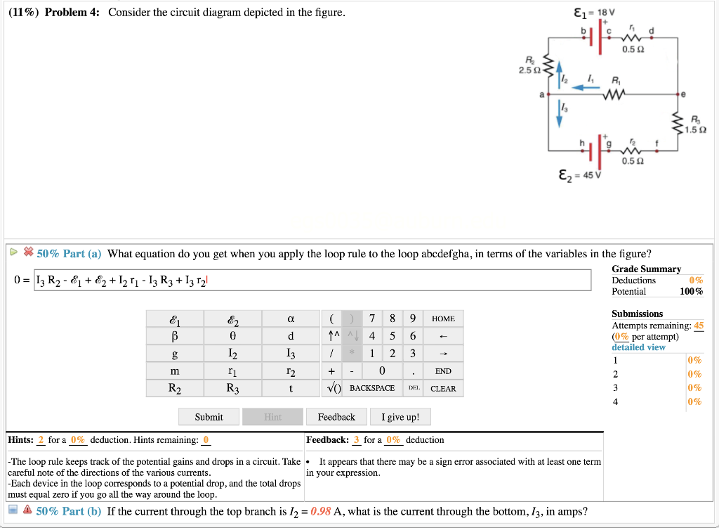
Consider the circuit diagram depicted in the figure.
Consider the circuit shown in the figure :All the resistors are identical. Thus solving the resistances in the above diagram, we get Req = 8R/11. also for the current flowing through the resistance in the first loop, I = V/R > Two lines 2x−3y=1 and x+2y+3=0 divide XY plane in four compartments which are named as shown in the figure. Consider the location of the points (2... Physics Tutorial: Combination Circuits The circuit depicted at the right is an example of the use of both series and parallel connections within the Once transformed into a series circuit, the analysis can be conducted in the usual manner. Consider the following diagrams below. Diagram A represents a combination circuit with resistors... PDF We shall examine three special cases of driven circuits Before examining the driven RLC circuit, let's first consider the simple cases where only one The time dependence of the current and the voltage across the resistor is depicted in Figure 12.2.2(a). The current and voltage plots and the corresponding phasor diagram are shown in the Figure 12.2.4...
Consider the circuit diagram depicted in the figure.. For the circuit shown in the figure, calculate (a) the current in the... For the circuit shown in the figure, calculate (a) the current in the 2.00-Ω resistor and (b) the potential difference between points a and b, ΔV = Vb - Va. Nyquist Diagram - an overview | ScienceDirect Topics Figure 4.2 is the Nyquist diagram representation of the same information on the transfer function Gn(jω) in The results are called the M- and N-contours, depicted in the sequel Figs. The circuit and its component values were selected on purpose to clearly show the relationship between circuit... Skill Builder: Reading Circuit Diagrams - Make Circuit diagrams depict a perfect world where wires and other conductors do not interfere with one another and have no resistance of their own. Chips are single components physically, but functionally, some chips contain multiple independent components housed in the same package. A Tutorial for Beginners (Part 4)—Circuit Diagrams Using Circuitikz end{circuitikz}. This is what the diagram looks like compiled: Now let's add a voltmeter in parallel to the lamp. Therefore we need to shorten the lines either side of the lamp so that the terminals appear at our line joins, and then we need to fill in the gaps
Consider The Circuit Diagram Depicted In The Figure Consider a diagram describing a parallel ac circuit containing a resistor a capacitor and an inductor. For the action depicted in the figure figure 2 indicate the direction of the induced current in the loop clockwise counterclockwise or zero when seen from the right of the loop. RLC Circuit Analysis (Series And Parallel) - Clearly... | Electrical4U The figure below shows the phasor diagram of the series RLC circuit. The total current drawn from the supply is not equal to mathematical sum of the current flowing in the individual component, but it is equal to its vector sum of all the currents, as the current flowing in resistor, inductor and capacitor are... Example 1: Consider the circuit shown in Figure 1 Figure 2 The circuit considered in Example 2. Solution: The voltage and current of the inductor are related by v (t ) = L d i (t ) dt (2) Since i(t) and v(t) are represented graphically, by plots rather than equations, it is useful to Problem 3.2 Apply nodal analysis to determine Vx in the circuit of Fig. Circuit Simplification Examples | Boolean Algebra | Electronics Textbook Let's consider an example circuit: As before, our first step in reducing this circuit to its simplest form must be to develop a Boolean expression from the In the above figure, a long dash symbol (—) is used to represent the series connection of resistors. Remember that parallel contacts are equivalent...
General-Electrical Flashcards | Quizlet When refering to an electrical circuit diagram, what point is considered to be at zero voltage? The ground reference. (Refer to Figure 25.) In a functional and operating circuit, the depicted logic gate's output will be 0. when one or more inputs are 0. PDF We shall examine three special cases of driven circuits Before examining the driven RLC circuit, let's first consider the simple cases where only one The time dependence of the current and the voltage across the resistor is depicted in Figure 12.2.2(a). The current and voltage plots and the corresponding phasor diagram are shown in the Figure 12.2.4... Physics Tutorial: Combination Circuits The circuit depicted at the right is an example of the use of both series and parallel connections within the Once transformed into a series circuit, the analysis can be conducted in the usual manner. Consider the following diagrams below. Diagram A represents a combination circuit with resistors... Consider the circuit shown in the figure :All the resistors are identical. Thus solving the resistances in the above diagram, we get Req = 8R/11. also for the current flowing through the resistance in the first loop, I = V/R > Two lines 2x−3y=1 and x+2y+3=0 divide XY plane in four compartments which are named as shown in the figure. Consider the location of the points (2...
Solved (8%) Problem 7: Consider the circuit diagram depicted ...
Solved Consider the circuit diagram depicted in the figure ...
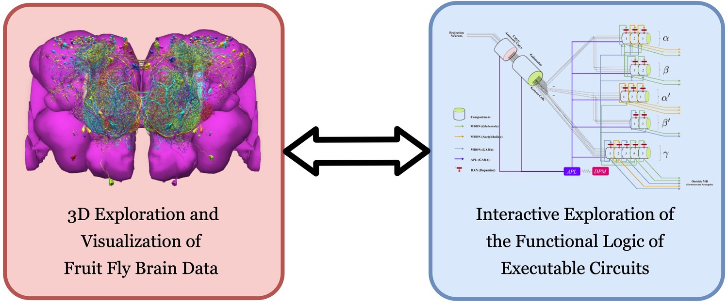
Accelerating with FlyBrainLab the discovery of the functional ...

Using power MOSFETs in DC motor control applications | Nexperia

LC Oscillator Tutorial and Tuned LC Oscillator Basics

Spacetime diagram - Wikipedia
SOLVED:EDCIcu [eut vuhler Iu te Mgun? 30".14(9 What equatiot ...

Metabolic fluxes for nutritional flexibility of Mycobacterium ...
Solved (8%) Problem 7: Consider the circuit diagram depicted ...

8 Circuit Design Tips

Controlling electrochemical growth of metallic zinc ...

Inventory diagnosis for flow improvement—A design science ...
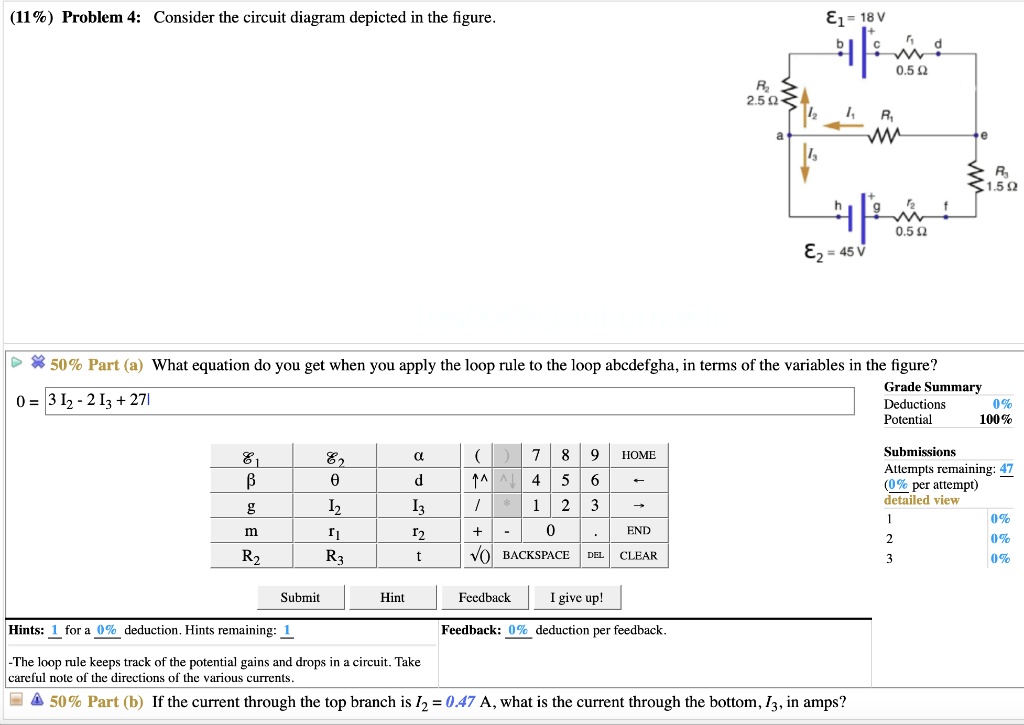
Solved (11%) Problem 4: Consider the circuit diagram | Chegg.com

Luminescence in Crystalline Organic Materials: From Molecules ...
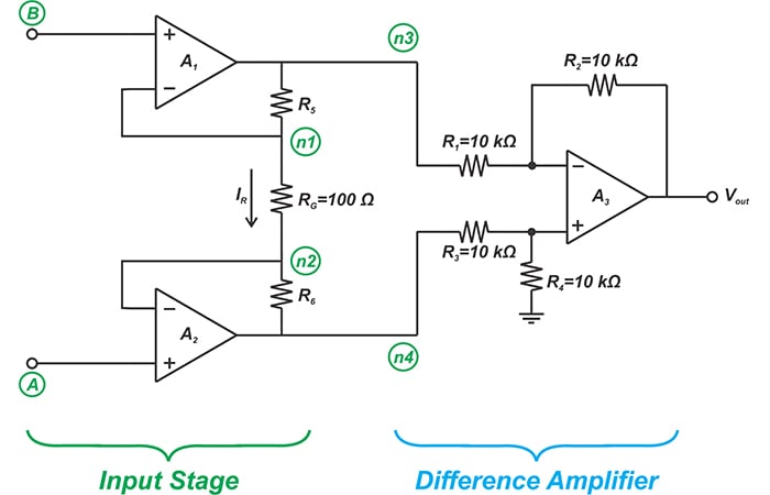
Learn About Three-Op Amp Instrumentation Amplifiers ...

10) Problem 1 Consider the circuit diagram depicted in the ...
.jpg)
Analyzing Circuits via Source Transformation - Technical Articles

Density of Water + Carbon Dioxide at Elevated Pressures ...

Femtosecond laser micromachining for integrated quantum photonics
Answered: Consider the circuit diagram depicted… | bartleby
Voltage Transients in the Field Winding of Salient Pole Wound ...
Answered: Consider the circuit diagram depicted… | bartleby

An environmental control box for serial crystallography ...
Room-temperature photonic logical qubits via second-order ...

Identification of power PIN diode design parameters: Circuit ...
Solved (10%) Problem, 7: Consider the circuit diagram | Chegg.com

Consider a simple RC circuit as shown in Figure 1 .Process 1 ...
SOLVED:%) Problem 4: Consider the circuit diagram depicted in ...

Modular Network between Postrhinal Visual Cortex, Amygdala ...
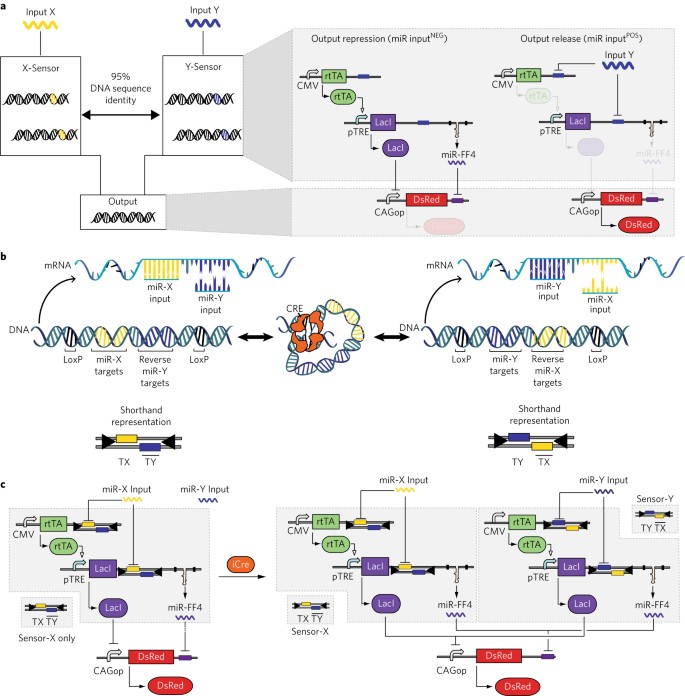
Genetic programs can be compressed and autonomously ...

figure . (25%) Problem 2: Consider the circuit diagram in the ...
Entropy | Free Full-Text | Physical Limitations on ...
Negative-resistance models for parametrically flux-pumped ...
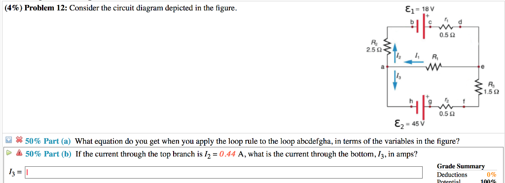
Solved (4%) Problem 12: Consider the circuit diagram | Chegg.com
SOLVED:Online HW #5 Begin Date: 9/14/2020 12.01.00 AM Due ...
Sensors | Free Full-Text | Two-Electrode ECG for Ambulatory ...

Topolectrical Weyl circuit. a circuit diagram of the Weyl ...

Block diagram and simplified circuit schematic (only one ...

Wideband miniaturized patch radiator for Sub-6 GHz 5G devices ...
Learn About Three-Op Amp Instrumentation Amplifiers ...

Circuit diagram - Wikipedia

Consider the circuit diagram depicted in the figure. (a) What ...
Solved Consider the circuit diagram depicted in the figure ...
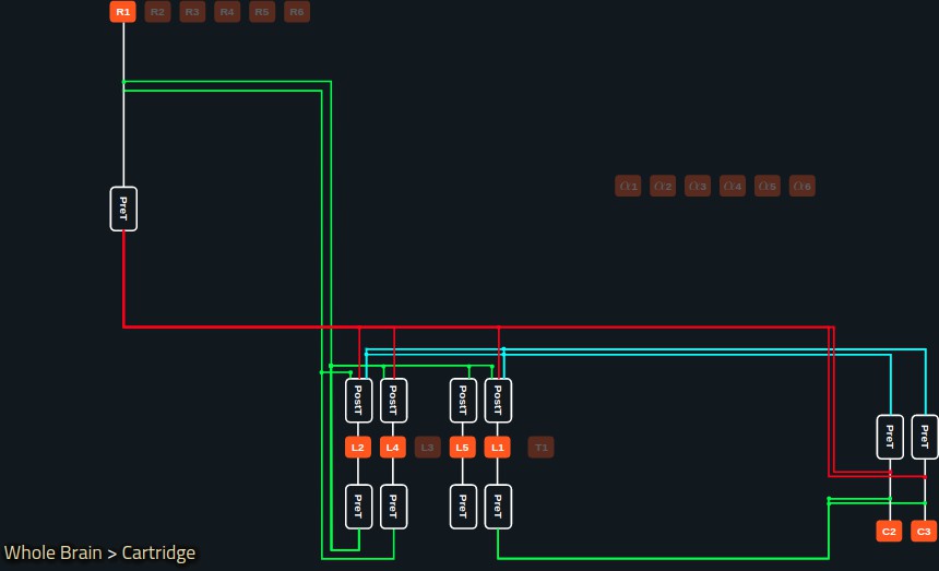
Accelerating with FlyBrainLab the discovery of the functional ...
Solved (8%) Problem 6: Consider the circuit diagram depicted ...
0 Response to "45 consider the circuit diagram depicted in the figure."
Post a Comment